5-1 Abstract:
Transmission towers are a vital element of the transmission system. However, natural environmental factors, such as wind and sun exposure, gradually corrode and damage tower structures over the years. Consequently, towers must periodically be replaced.
Old transmission towers are typically replaced in one of two common ways. In the first method, power is turned off in all transmission lines on the old tower. Lines are then switched to the new tower one by one. Unfortunately, this “power outage method” reduces system scheduling flexibility and increases operating risks. In the second method, temporary poles and lines are erected. This method requires additional land to accommodate temporary poles. It may be more difficult in some areas with poor land.
The “tower wrapping replacement method” proposed in this article solves the difficulties associated with both conventional replacement methods. It not only avoids the simultaneous power outage of transmission lines but can also be applied flexibly to any location. This method enables the power transmission system to accomplish the replacement of old transmission towers with the lowest possible impact.
5-2 Introduction to the Tower Wrapping Replacement Method:
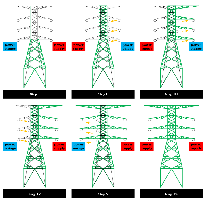
As the name suggests, the tower wrapping replacement method, installs the new tower around the outer side of the old transmission tower and gradually replaces it. The method entails the following steps (also outlined in Figure 1):
First, install new tower angle irons on the existing foundation of the old tower. Next, set up the new tower footings on the new angle irons. When power is turned off on the left side of the old tower, the left side of the new tower’s body is installed.
When power is restored to the left side of the old tower, power to the right side can be turned off. The right side of the new tower’s body can then be installed. Additionally, power lines can be moved to the right side of the new tower. Once the lines have been shifted, the old cross-arm can be removed from the right-side of the old tower.
A new cross-arm can be installed on the right-side of the tower. Wires can then be moved to the new cross arm.When power is restored to the lines on the right-side of the tower, the power can again be cut to the left side of the tower. The lines from the old, left cross-arm can then be moved to the left-side of the tower body. After the lines are shifted, the old cross-arm can be removed from the left-side of the tower.
The new cross-arm can then be installed on the tower’s left side and power lines can be moved onto it.A new cross-arm can be installed on the right-side of the tower. Wires can then be moved to the new cross arm.
When power is restored to the lines on the right-side of the tower, the power can again be cut to the left side of the tower. The lines from the old, left cross-arm can then be moved to the left-side of the tower body. After the lines are shifted, the old cross-arm can be removed from the left-side of the tower.
The new cross-arm can then be installed on the tower’s left side and power lines can be moved onto it.
Finally, the body of the old tower can be removed and power can be restored to the left-side of the new tower. This completes the replacement process.
5-3 Advantages and Prospects:
The greatest advantage of the Tower Wrapping Replacement Method, proposed here, is that it does not involve either simultaneous outages or land acquisition. During the replacement process, power lines on at least one side of the tower can maintain a continuous power supply. These features allow this method to greatly alleviate the above-mentioned difficulties while loosening the time and space constraints on the replacement of old transmission towers, thereby increasing the flexibility of maintenance work