Monitoring & Control
Distribution Dispatch Control Center(DDCC)
4.1 Introduction of Distribution Dispatch Control System (DDCS)
Supervisory control system is a specific device capable of providing executive control and confirm whether the command is executed. Supervisory control system usually designed to collect large amounts of data, related to the operational information of the entire power system, commonly known as Supervisory Control and Data Acquisition (SCADA) System.
The comprehensive automation of power dispatch and control refers to the Hierarchical Dispatch Control System(HDCS). According to the power dispatching operation, it is divided into three levels: Central Dispatch Control System (CDCS), Area Dispatch Control System (ADCS), and Distribution Dispatch Control System (DDCS), responsible for the supervisory control and operation of 345 kV, 161/69 kV, and 22/11 kV systems. The operation and maintenance are respectively carried out by Department of System Operation, each Power Supply Branch belong to Department of Power Supply, and each Branch belong to Department of Power Distribution (totally 23 Branches).
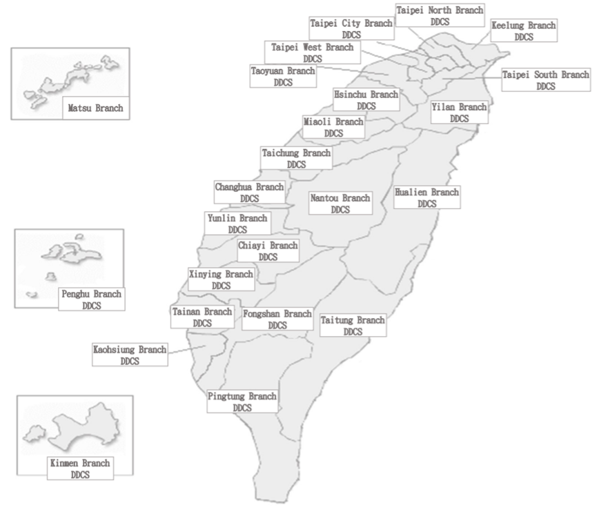
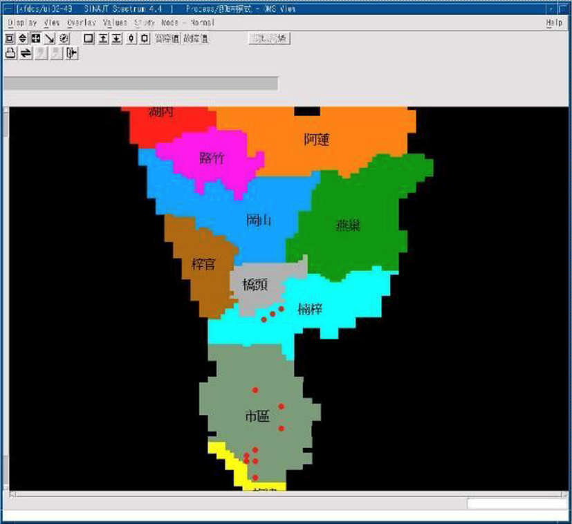
Figure 4.1 Distribution map of Distribution Dispatch Control System (DDCS)
The comprehensive automation of power dispatch and control takes the computer equipment of the dispatch control center as the core, takes the substation as the end. Information terminal equipment (Remote Terminal Unit, RTU) installed in the substation, which connected with the computer equipment of the dispatch control center through communication lines, is responsible for providing information of equipment in the substation and accepting operation command. As to achieve the comprehensive automation of supervisory control and data acquisition.
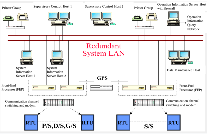
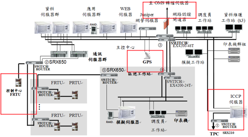
Figure 4.2 Architecture diagram of Distribution Dispatch Control System (DDCS)
The functions of SCADA system includes: Data Acquisition, Data Processing and definition, Supervisory Control, Alarm Display and Control, Periodic Collection and Reports, Sequence-of-Event Recording, Trend, and Man-Machine Interface.
The work of the duty personnel in the Distribution Dispatch Control Center (DDCC) includes: Supervisory Control and Data Acquisition, Emergency Load Shedding and Partition Rolling Blackout, Street Lights On/Off and Lighting Management in Substations, Voltage Control, Inactive Power Device Control, Lower-Voltage Operation Control, Operation Data Query, Air Defense Intelligence and Lights Control.
4.2 Introduction of ADMS
(1) According to the description of the SMART GRID INDEX document 2.1 Monitoring & Control, Monitoring & Control is divided into three stages: SCADA, DMS, and ADMS. The ADMS functions should include on-site real-time data collection and control (SCADA), Automatic fault location, isolation and supply restoration(FLISR) and outage management system (OMS) application. Taiwan Power Company has developed various power distribution application management systems since 1992. As of the end of December 2023, it has established outage management system (OMS) and Feeders Dispatch Control System (FDCS) with functions such as SCADA, FDIR (Automatic Fault Detection, Isolation and Restoration , or called FLISR),and feeder single line diagram and GIS (geographic map information) in 23 Distribution Branches, covering 9,045 automated feeders 32,296 automatic switches included, the proportion of automated feeders has reached 90%; the whole 23 FDCS systems in operation are equipped with ADMS functions, the automatic Fault location, Isolation and Service Restoration (FLISR), described in SMART GRID INDEX file 2.1 Monitoring & Control.
(2) In response to Taiwan’s goal of 20% renewable energy in 2025 and the “Smart Grid Overall Planning Plan” in 2030, the number of downstream power recovery units will account for 90% of the total number of power restored within 5 minutes, the traditional distribution network will face the impact of renewable energy on the distribution network Stable power supply and the ratio of the number of restored power units have more stringent requirements on dispatching efficiency. However, the distribution-level dispatching system is set up, but it need the new system control function corresponding to the distributed power supply (including renewable energy) and the newly expanded smart grid function application. Therefore, it is planned to build a new generation of advanced distribution management system (ADMS) to integrate multiple operation information [such as distribution map, smart meter (meter data management system), solar photovoltaic, microgrid, electric vehicle (distribution-level renewable energy management system) , fault indicator (FCI) and distribution transformer terminal equipment (TTU) and other information], introduce smart grid control functions to optimize distribution scheduling, reduce grid connection impact, maintain distribution network stability, and delay traditional distribution equipment (transformers, feeders, etc.) due to power supply demand The construction time and service life are required to improve the quality of electricity and the construction efficiency of power distribution equipment. Therefore, in 2019, the company began to plan and design ADMS systems that comply with renewable energy regulation. In 2020, standardize the technical content and in line with the development trend of ADMS in the world. In June 2021, the tender is officially announced, and the case will be decided in January 2022. The winning bidder is the ADMS development team composed of MINSAIT ACS, Taiwan Fixed Network and Xiangzheng Company. The construction period is 3 years and it is expected to be launched by the end of 2024.
The process of building an advanced power distribution management system
- Since 1995, TPC introduced the FDCS system software, and built it on a trial basis in North-South (Nihon Vending system) and Taichung (MINSAIT ACS system) Distribution Branch between 1995 and 2002. The two systems have been equipped with monitoring and control, data collection, and line fault detection, isolation and restoration functions and feeder schematic diagrams. During operation in the two Distribution Branch, fully obtained valuable experience and verify the feasibility and benefits of system operation.
- In order to integrate the functions of Distribution Feeder Automation, SCADA, fault detection, isolation and restoration(FDIR/FLISR) and Outage management system(OMS) providing for Distribution dispatching in each Distribution Branch, TPC decided to purchase different FDCS system in 2003 at the North-South and Kaohsiung Distribution Branch. To verify the different brand of FDCS system for the integration of SCADA, FDIR and OMS specific ways, TPC had evaluated the two brands of system through FDCS indicators by people who has experience and practical in distribution network operation. To select the suitable one for operation in Taiwan distribution network, as the distribution system operating standards in Taiwan.
- In 2007, the winning FDCS system (Siemens) that was built in Kaohsiung District Districts was selected to promote all Distribution Branch in the Taiwan. The FDCS system acceptance project was carried out in Taoyuan County, and a team composed of inter-departmental and academic staff from TPC was responsible for functional verification. At the same time, the ICP training plan (Industrial Corporation Program, ICP) was carried out, and the maintenance and operation technology was transferred to TPC. For the specific construction process of TPC FDCS system, please refer to the following table 4-1.
In 2007, the FDCS system (Siemens) of the winning Kaohsiung Distribution Branch will be selected to promote power distribution areas throughout Taiwan. The FDCS system acceptance project was carried out in Taoyuan County.
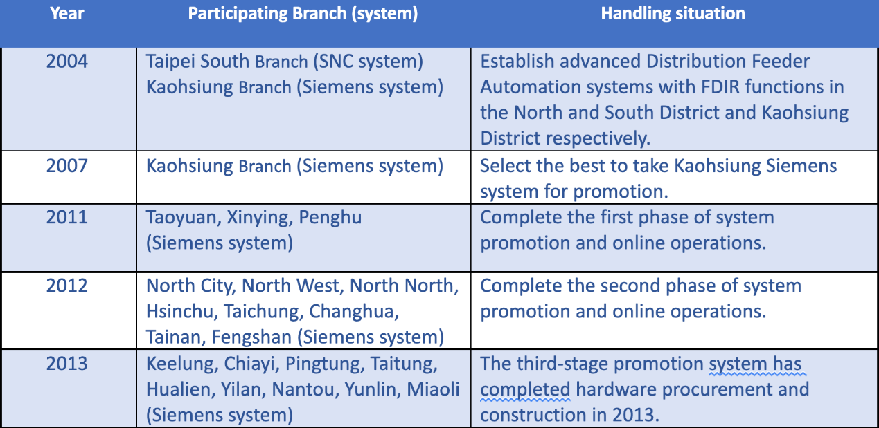
Table 4.1 TPC FDCS system establishment process
Current implementation of FDCS system-wide environment
There are currently 23 FDCS systems in operation and their distribution is shown in Figure 4-1. The system has been built successively since 2004, which can provide the ADMS functions required by Taiwan’s 22kV and 11kV power distribution feeders.
The FDCS GIS database is updated from OMS to the FDCS system by incremental update at least twice a week. The data will be verified in OMS before the data is imported into the FDCS system, and the imported data will also be verified before launching it into the real-time database of FDCS system.
In the 4 Distribution Branch, Taipei City, Hsinchu, Miaoli and Kaohsiung, the FDCS system monitors both the Meshed network and the Redial network. The FDCS systems in all other Distribution Branch only monitor the normally Redial network. The FDCS system can automatically perform fault detection and isolation and upstream power recovery, or provide options to be executed after the plan is confirmed by operators, and provide downstream power recovery recommended operating steps.
FDCS system provides dispatcher training simulator (Dispatcher Training Simulator, DTS), which can be used for time-testing training of operators in daily dispatching operation exercises. All operators must test different power outage scenarios in the DTS server.
FDCS performs local and remote backups daily and weekly to improve the reliability of the dispatch system.
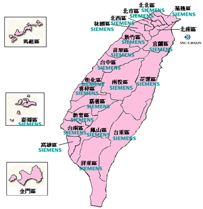
Figure 4.3 Automated system build distribution map
Existing system architecture
The FDCS system is applied to the power distribution system 11.4Kv and 22.8kV overhead and underground Redial network distribution feeders. The feeder dispatching control center’s servers monitor the operation of the distribution line through the communication system and the feeder information terminal equipment. When the line fault occurs, it can quickly and automatically isolate the line fault section, automatically restore the power supply of the line's sound section, and provide GIS map information for the dispatcher and the on-site repair personnel to the area affected by the accident.
Existing system Function Description
Control center: It mainly provides SCADA+FDIR functions, and has geographic map data (GIS) processing capabilities, providing operators with complete operation screens and dispatching information; and when an accident occurs, it can assist operators to quickly restore upstream and downstream sound sections to restore power. The expansion capacity provided by the system allows feeders and substations in the whole district to be included in the scope of Distribution Feeder Automation.
Field equipment: It can monitor various substation information terminal equipment (FRTU), feeder information terminal equipment (FTU) and other equipment installed on Redial network means or Meshed network.
Supervisory Control And Data Acquisition (SCADA) function
- Monitor and control of automated switches, and devices within substation
- Map type display for electrical network topology
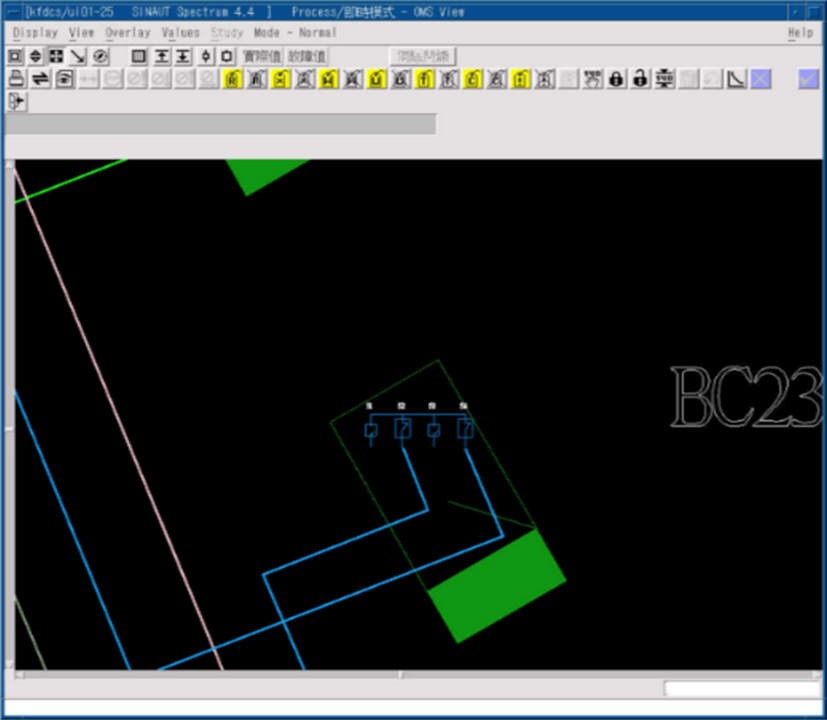
SCADA provides GIS display for operation
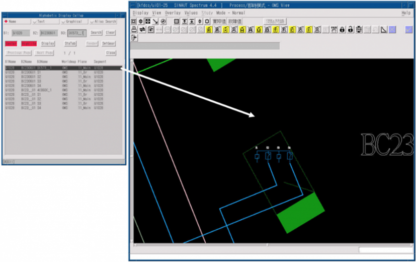
Device Location Function
Easily navigate to required display from alarm event list, equipment tag, road name, landmark, etc.
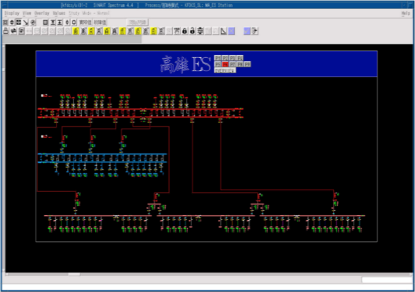
Feeder Schematic Display(SLD)
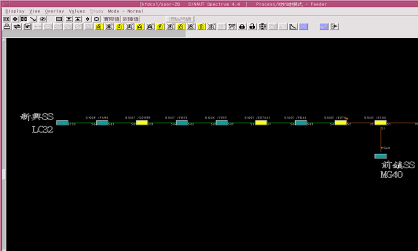
Feeder schematic display based on electrical network topology
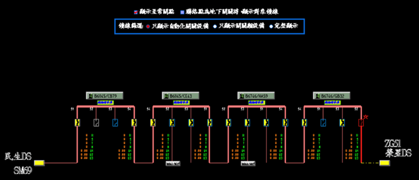
Circuit Breaker status on feeder schematic display based on electrical network topology
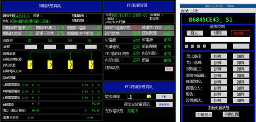
Circuit Breaker operation display with integrated information
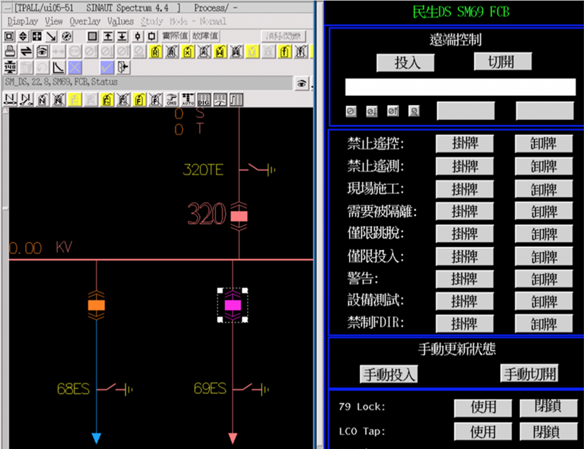
Integrates various types of information on operation display
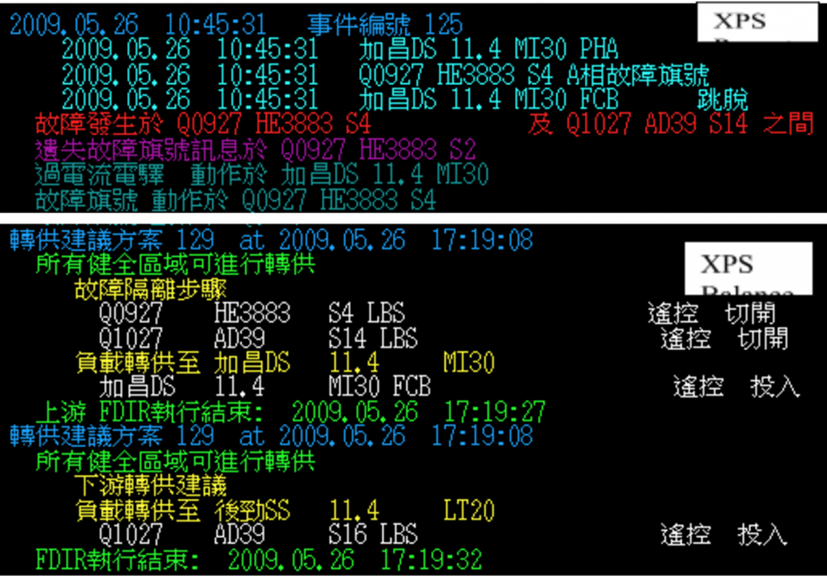
Incident detection, isolation and power recovery (FDIR)
- Automatic/manual detection of accident zones, isolation and upstream power recovery, and provision of re-supply schemes
- Disable all or part of the FDIR function for the entire system/substation/feeder as a unit
- Natural disasters: FDIR prohibition of the whole system
- Substation/main transformer shutdown inspection: disable inspection of feeder FDIR
- Incident handling: FDIR of the accident feeder is disabled or FCB is prohibited from being listed
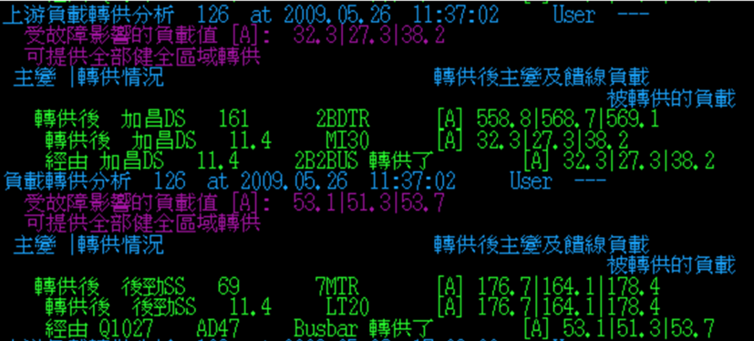
- Simulated accident transfer plan
- Simulation of BUS failure (main transformer failure) calculation and transfer plan
- Designed with Redial network distribution system
- The feeder of the Meshed network system must be set to prohibit the implementation of FDIR function
- The plan will include the judgment of the fault current direction and strengthen the FDIR function
- Software will check the updates in OMS and export into supported format to import into FDCS databse.
- Circuit breaker status in FDCS can feedback to OMS system.
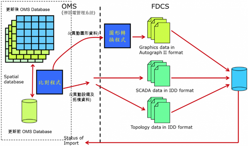
Figure 4.4 Architecture for database incremental update and information exchange
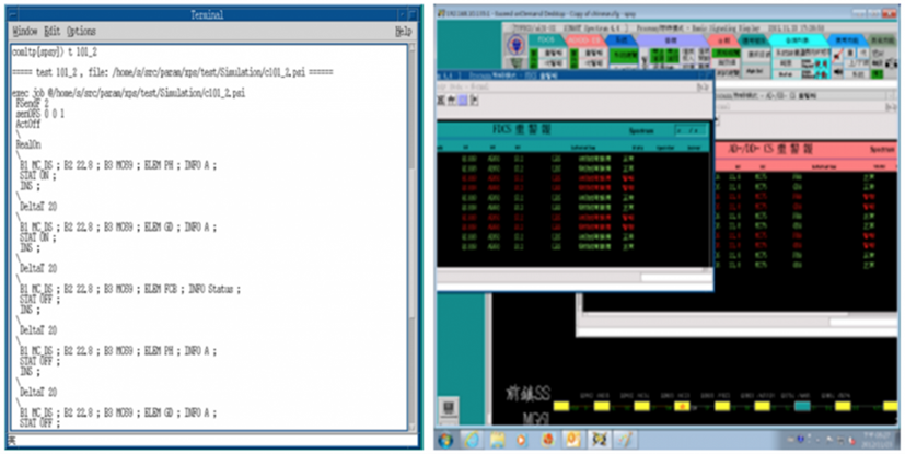
FDCS DTS
Communication Protocols
- ICCP communication (DDCS to FDCS)
- FTP (OMS/DMMS and FDCS conversion files)
- NTP (time synchronization)
- DNP3.0 (downstream communication protocol)
- TCP/IP (10/100/1000Mbps) and UDP (device communication)
Existing system communication architecture
- There is a wide area network (WAN) backbone network between the control centers (distributed as shown in Figure 4.5) planned for all 23 Distribution Branch in Taiwan, and the control centers in all 23 Distribution Branch in Taiwan have local area networks (LAN). The connection is available for data transmission. The backbone network includes optical fiber and optical fiber composite overhead ground wire (OPGW).
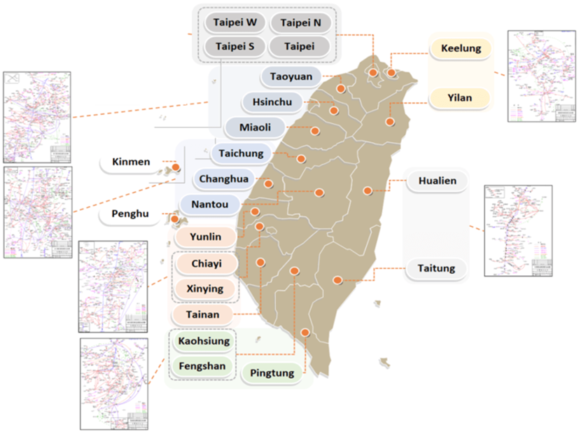
Figure 4.5 Overview of the distribution of control centers in the power distribution area
The current communication protocols used for field monitoring equipment are DNP3.0, DNP3.0 Over TCP/IP (Figure 4.6).
DNP3.0 is a communication protocol widely used in the industry. The FDCS use DNP3.0 over TCP/IP as the communication between the control center and FRTU and DNP3.0 as the communication between FRTU and PRTU/FTU. When the IEC61850 communication protocol product types and brands increase, the automation equipments and protection equipments in field can adopt this communication protocol to simplify field wiring and data maintenance. As the TCP/IP communication architecture is widely adopted by various wired and wireless communication equipment, the FDCS system of the power distribution feeder uses TCP/IP as the communication architecture.
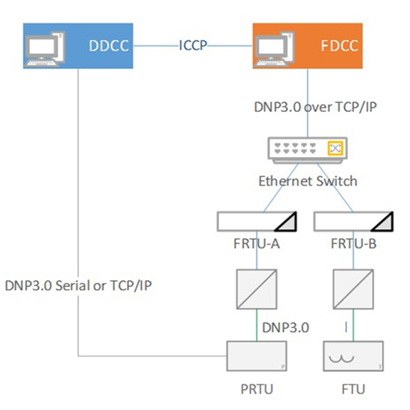
Figure 4.6 Communication between control center and equipment
- According to the goal set by the “The Smart Grid Master Plan” of the Bureau of Energy, Ministry of Economic Affairs, 1500 automatic switches monitored must be increased every year from 2022 to 2030. It is expected that the goal of full automation will be achieved by 2030. At present, the total number of automated feeders by the end of 2023 has reached 9,045, and the penetration rate is about 90%. 32,296 feeder automatic switches have been included in the FDCS system monitoring (Figure 4.7).
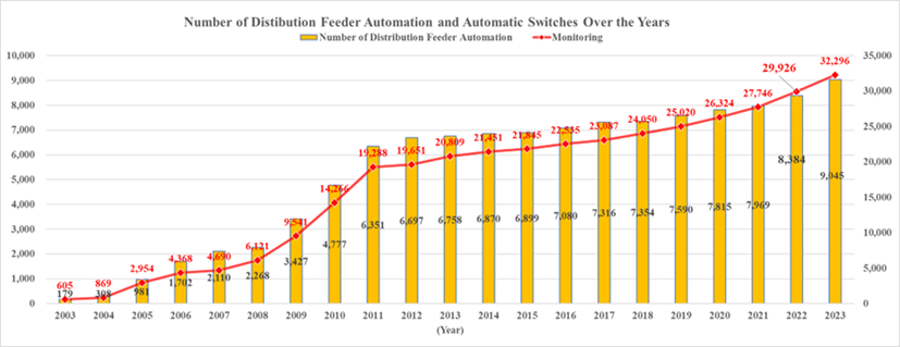
Figure 4.7 The actual performance of the number of automatic feeders and the number of switches
The main benefits of Distribution Feeder Automation include reducing manual on-site operations, accelerating power recovery time, reducing operating costs and improving work safety.
Statistics of the number of remote control operations for work and accidental power outages over the years
Application computer, communication, control and other technologies and technologies to build a feeder FDCS system to perform real-time status monitoring, power remote measurement and remote operation of automatic switches of distribution feeders. According to statistics, from 2007 to 2023, the number of operations due to power outages increased from 230 to 6,678, and the number of maintenance operations increased from 6,493 to 101,456, enabling operators to grasp and dispatch power distribution feeders at any time, quickly isolate faults, reduce the scope of power outages, and greatly Reduce the time for dispatching personnel to work on-site in the event of a power outage, and improve the efficiency of the operation of the distribution grid.
Smart grid overall planning model scheme “The proportion of the number of units restored within 5 minutes at the downstream end”
According to the content of my country’s “Smart Grid Master Plan”, the automatic feeder restoration (FDIR) is formulated, and the downstream end of the accident restoration time will account for the number of all automatic feeder restorations from 5 minutes to 17%, and the target will be increased to 2022. 35% within 5 minutes in 2025; 70% within 5 minutes in 2025; 90% within 5 minutes in 2030, and the company has reached 57% in 2023(Figure 4.8).
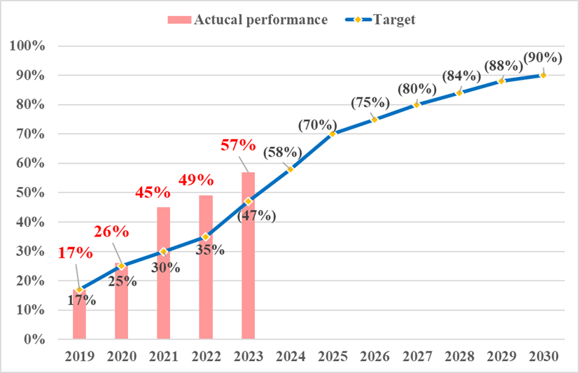
Figure 4.8 The percentage of recharges completed by the automated system within 5 minutes
Improve ADMS system (FDCS system) in response to the future development of smart grid
- Taiwan is actively promoting the policy of establishing a nuclear-free home by 2025and has set a new goal of increasing the proportion of renewable energy power generation to 20% by 2025. Renewable energy brings the hope of energy transition. TPC has to deal with the grid shock caused by the high penetration rate distributed power supply (DER) in advance.
- In order to create a friendly grid-connected environment, Taiwan Power Company has successively started grid improvement projects to increase the grid-connected capacity of renewable energy, and to avoid the impact of the uncertain characteristics and intermittent characteristics of renewable energy on the grid after the renewable energy is connected to the distribution network. Plan to integrate the power distribution FDCS system and the renewable energy management system and improve the flexibility of dispatching operation through its ability to monitor and integrate various information of the power distribution network.
ADMS continues to improve as a plan
Integrate the Data for many distribution systems of TPC
- TPC has commissioned the Taiwan Industrial Technology Research Institute to conduct research on the introduction of Common Information Model (CIM) into smart grid application systems in 2019, and completed the CIM profile (CIM Profile) specification for TPC to build and integrate various The distribution monitoring system information is in the data application analysis platform.
- TPC has also commissioned Taiwan Industrial Technology Research Institute to complete the GIS CIM profile format of the power distribution system. TPC will continue to implement the CIM format data exchange file (CIM Message) of each system of TPC according to this standard.
ADMS system continues to promote
- The plan for a new generation of ADMS system has been completed in 2020 to replace the existing FDCS (with ADMS function), and will integrate various power distribution subsystems, GIS map Integration of resources and OMS, FLISR (utilize power flow calculation), Distribution Power Flow calculation, Distribution State Estimation, Feeder Reconfiguration, Active Network Management and other smart grid functions.
- In 2021, the planned ADMS content is entrusted to DNV International Consulting Company to formulate feasible technical specifications, and the public request for comments (RFC) and public request for quotation (RFQ) of technical specifications will be processed. There are international ADMS manufacturers such as Schneider, GE, ABB and MINSAIT ACS. Participate in providing comments on the content of the specifications. In January 2022, the bid is awarded. It contracted by MINSAIT ACS, Taiwan Fixed Network and Hsiang Cheng Electric. It will promote the upgrade of the power distribution system and introduce the MINSAIT ACS PRISM ADMS system. The project is working on solution design in 2022 and it is expected to be launched in 2025.
Implementation of smart grid application functions
- Take the lead in integrating renewable energy across the island
TPC is the first to pilot the introduction of a new generation of ADMS in Kinmen District in 2020 to monitor renewable energy, collect and integrate multiple information on the distribution network. Through the application of the pilot platform, TPC has the ability to manage and control the grid connection of renewable energy. Kinmen ADMS has completed the data capture of the Kinmen renewable energy case (82 PV-GATEWAY installations with a capacity of about 6MW, 2 DG-RTU stations with a capacity of about 3.3MW), accounting for more than 90% of the total installed capacity of Kinmen solar energy, and also captured the Jinmen civil rights feeder 50 Data of distribution line transformers with TTU (the maximum feeder load is about 2.5MVA), in order to completely collect the renewable energy data and user-end power data in Kinmen area, and fully grasp the fluctuation of the system terminal voltage and load.
- Import IEC61850
In the Kinmen area, the initial stage will be conducted in the form of a research project. The implementation of the IEC61850 communication standard will collect and monitor the renewable energy information of the photovoltaic (PV) field, and the pilot FTU will use IEC61850 communication.
- Verification of FDCS smart grid application functions
Introduce advanced technologies such as power flow analysis and state estimation, and integrate smart monitoring equipment such as smart meter (AMI), transformer information terminal equipment (TTU), fault indicator (FCI), etc., to carry out distribution feeder automation SCADA, FDIR, load forecasting and regeneration The verification of advanced functions of power distribution network management, such as energy management and control, has been completed in 2020.
Figure 4.9 Function discussion
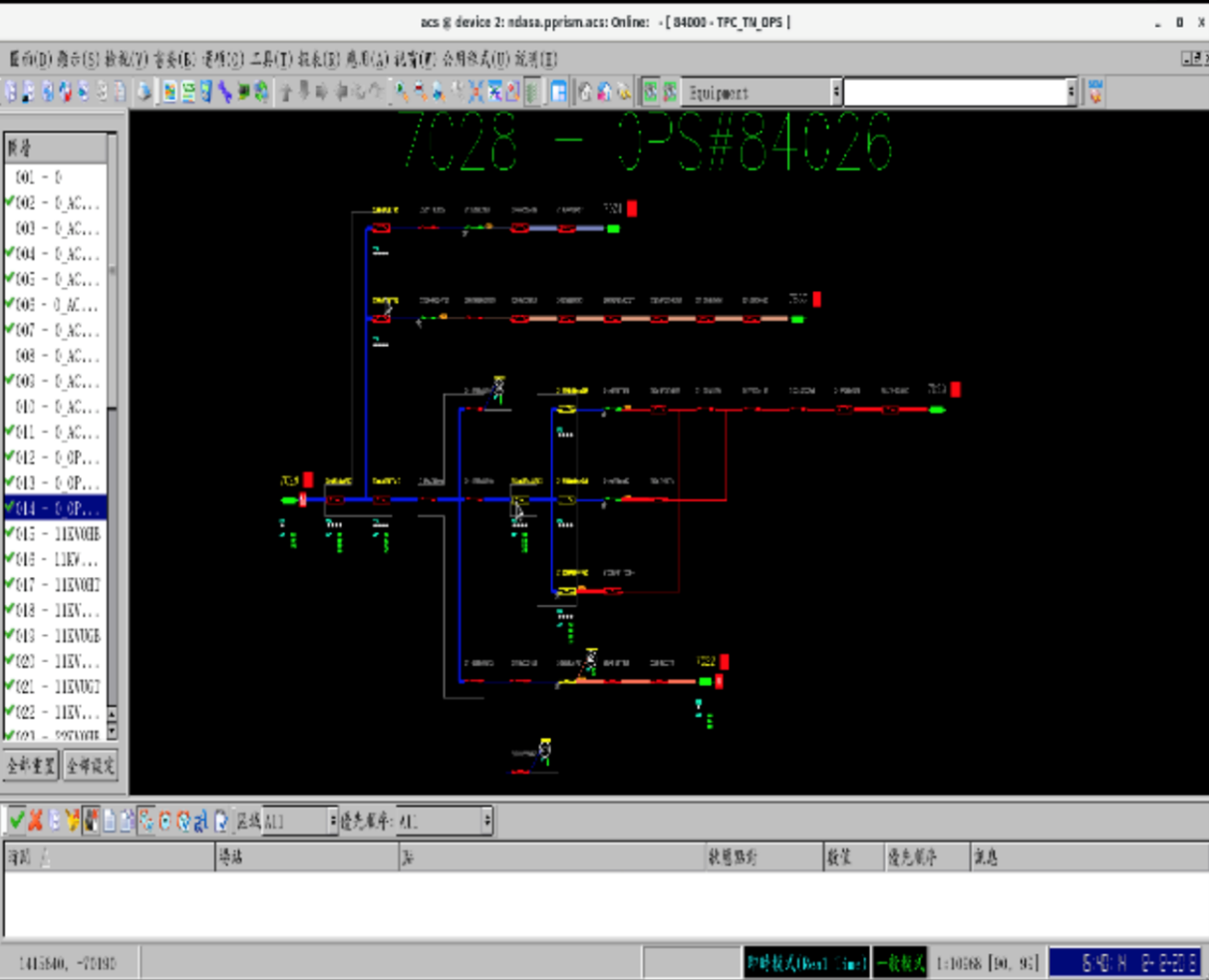
System one-line diagram
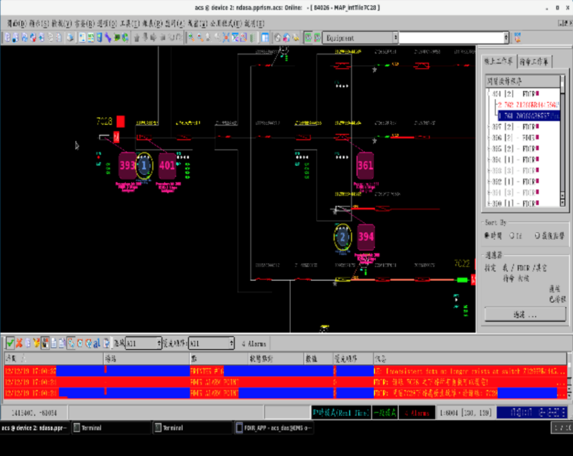
Accident transfer
Power flow analysis
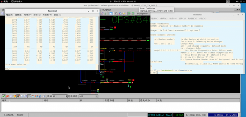
Figure 4.10 System diagram control screen
TPC and the Institute of Nuclear Energy Research, Atomic Energy Council, Executive Yuanjointly develop smart grid application functions, start cross-industry cooperation between domestic power companies and institutes, conduct research on feeder dispatch related technologies for high proportion of renewable energy, and has been developed conduct pilot in Yunlin Distribution Branch.
- Complete the integration of distribution power flow calculation program in FDCS System
In 2020, complete the integration of the distribution power flow calculation program on FDCS System, and propose a feeder transfer proposal, integrate the feeder power flow and line loss programs, and use the feeder test and FDIR in Yunlin area to adjust the feeder margin, Information such as the minimum and maximum voltage mark and location, line loss, etc., will be included in the forwarding plan for operators’ reference.
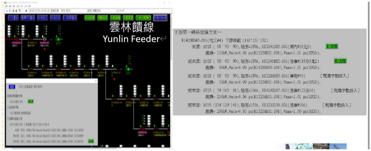
Figure 4.11. Proof of tidal current calculation showing daytime surface
In recent years, as a large number of renewable energy sources are connected to the grid, the intermittent nature of their power generation has led to problems such as voltage fluctuations and three-phase imbalance in the distribution system. When an accident occurs on the feeder, the renewable energy power generation device will suspend power supply, making it difficult to transfer power downstream of the fault point when the load is too large. To this end, an optimal configuration strategy platform for distribution feeder tie switches was developed to equalize the feeder load by adjusting the opening and closing state settings of the tie switches of each feeder in the substation. Taking the substation in Taipower's Yunlin District as an example, the simulation results verified that the regional feeder load rate could be equalized, so as to avoid excessive load in the downstream healthy area of some feeders, thus facilitating the smooth transfer of faults.
- Renewable energy reverse power transmission control function
Summarize the capacity and location of the renewable energy installations and equivalent them to the main line. Use the distribution power flow analysis program to verify the reverse transmission of the renewable energy, showing that the final FTU voltage is higher than the previous one
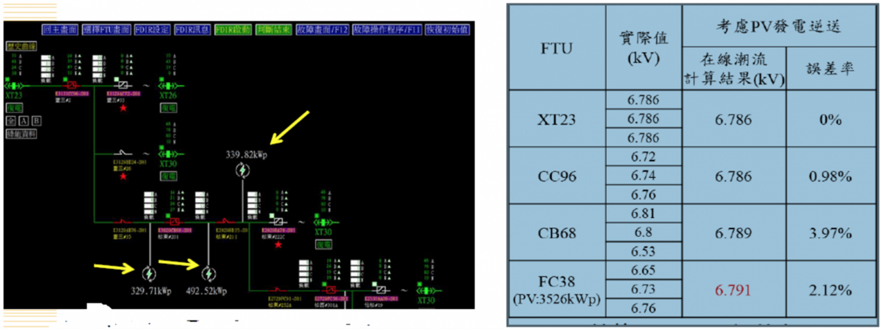
Figure 4.12 Reverse power transmission control of renewable energy
In a complex power distribution system, due to the large number of nodes in the main feeder and branch lines, if you want to master the information of each node, you must install a lot of measuring equipment, which not only increases the cost, but also has a large amount of data in the transmission and collection. certain difficulty. When the proportion of renewable energy is gradually increased, and the node measurement data is limited, it is bound to be difficult to grasp the voltage rise caused by renewable energy power generation, which will affect the quality of power consumption. Therefore, a state estimation technology is developed. This technology can estimate the power generation state of the main and branch lines of the power distribution system, and compare the error value between the estimated result and the on-site measurement value, and at the same time display the estimated result in the geographic map data system ( As shown in Figure 4.12), to help dispatchers grasp the influence of distributed power supply on feeder changes, and check the location of abnormal monitoring equipment.
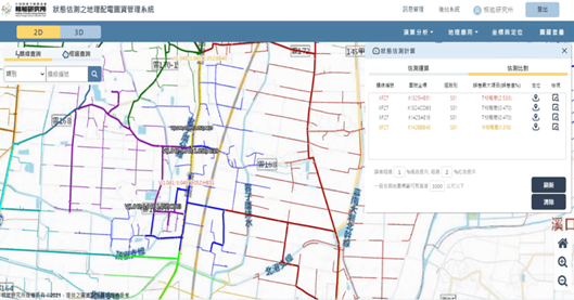
Figure 4.13 Geographic map data system
- Integrate the GIS function integration of the open map platform
The development of the spatial database function of converting data in Oracle into PostgreSQL (open source) has been completed. FDCS feeder data and equipment attributes can be integrated in various open maps (Figure 4.13) to achieve smart grid GIS data application.
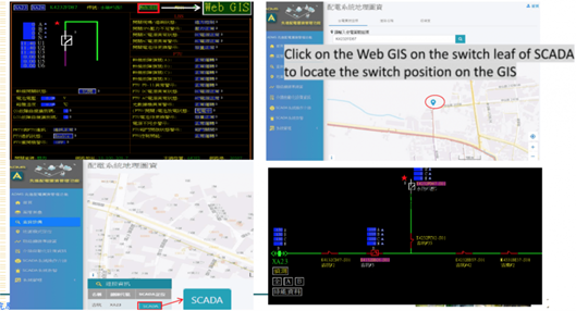
Figure 4.14 Dispatching system geographic map and single-line diagram
Develop a visual feeder dispatching management platform (as shown in Figure 4.14) to provide real-time visual information for dispatchers and emergency repair personnel when faults occur. This technology refers to IEC 61968 and IEC 61970 international standards to formulate a common information model for power distribution equipment. And use the common data format of the common information model to establish the integration of power monitoring and geospatial information, so as to reduce the error between the one-line diagram of the feeder operation on the distribution map and the field equipment, and ensure its correctness and operability.
Develop a visual feeder dispatching management platform (as shown in Figure 4.14) to provide real-time visual information for dispatchers and emergency repair personnel when faults occur. This technology refers to IEC 61968 and IEC 61970 international standards to formulate a common information model for power distribution equipment. And use the common data format of the common information model to establish the integration of power monitoring and geospatial information, so as to reduce the error between the one-line diagram of the feeder operation on the distribution map and the field equipment, and ensure its correctness and operability.
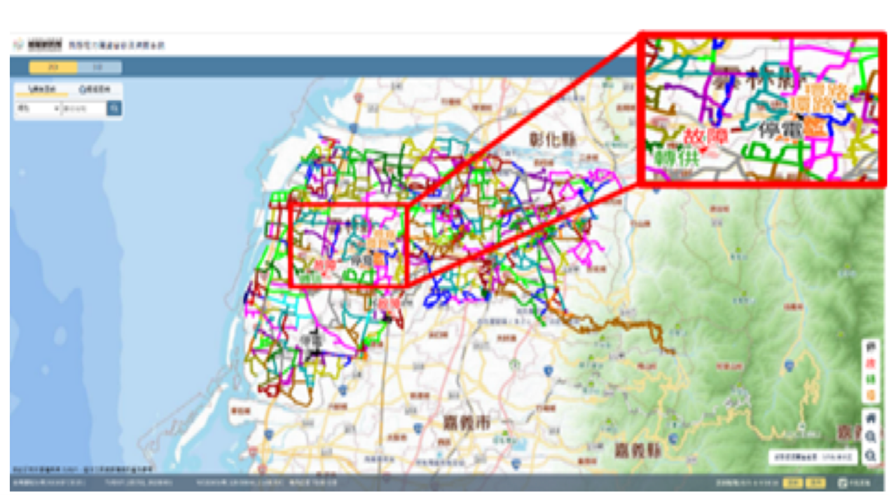
Figure 4.15 Visual feeder scheduling management platform