Real-Time Damage Monitoring System
1. Introduction
Nowadays, in response to the booming use of renewable energy, smart power generation has played an important role. Taipower is actively seeking various test fields to develop a new generation of smart power generation, including Real-Time Damage Monitoring System (RtDMS) for Unit 9 of Taichung Power plant, condition monitoring and diagnostic system for HV motors of Taichung Power Plant, Boiler Monitoring and Diagnostic Platform for Unit 5 ~ 8 of Taichung Power plant, etc. The more intelligent power generation applications we use, the better power service and stability we can provide.
2. Real-Time Damage Monitoring System
In the past, Taichung Power Plant experienced several boiler tube leakage accidents, which caused the power supply system in a critical situation. Consequently, we built the Real-Time Damage Monitoring System (RtDMS) for Unit 9 of Taichung Power Plant. With these pilot projects, we provide an innovative approach which achieves predictive maintenance boiler to smart power generation.
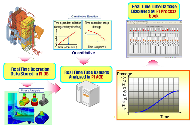
2-1 What is RtDMS
- RtDMS for boiler tube provides creep damage information of each tube of super-heater or reheater operated in high temperature and high pressure.
- The instantaneous creep damage of RtDMS is used for short term overheat creep damage detection which development is rapid until tube rupture occurs.
- The cumulative creep damage of RtDMS is used for tube life assessment with field examination of Non-Destructive Test which is more accurate than the life assessment based on statistical average operating data.
2-2 Applications of the RtDMS
Application 1:
- Ultra Super Critical(USC)(1,000MW) Boiler Case : New Boryeong Thermal Power Plant #1, 2,Korea( Doosan Heavy Industry)
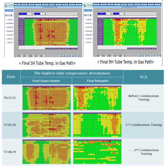
- RtDMS is installed to monitor final superheater and final reheater tubes.
- More than half of tubes in final superheaters and a few tubes in final reheaters in dangerous conditions were found during commissioning.
- DHI complete combustion tuning early to prevent short term overheating creep failure of final superheater and reheater tubes.
Application 2:
- Super Critical(SC)(500MW) Boiler Case : Hadong Thermal Power Plant, #1 & 4,Korea (CE & Doosan Heavy Industry)
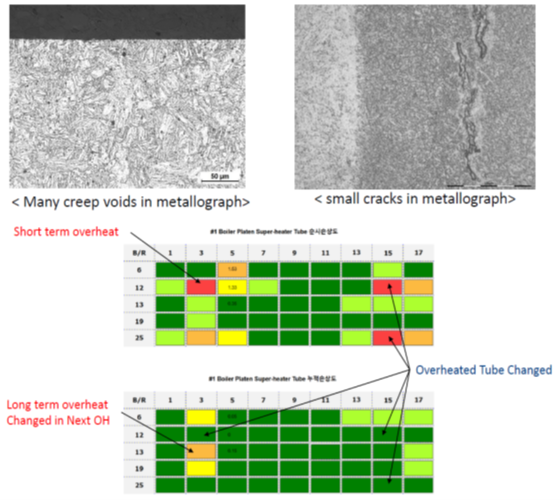
- RtDMS is installed to monitor platen superheater tube which is vulnerable to long term creep damage.
- RtDMS has found a tube in a dangerous condition for a long time, so metallographic replication is carried out and many creep voids is observed.
- If creep failures occur in the same type of boilers, metallographic replication is carried out according to the cracks found by the RtDMS.
Application 3:
- SC(500MW) Boiler Case : Dangjin Coal Fired Power Plant #1 & 4, Korea(CE & Doosan Heavy Industry)
- RtDMS is installed to monitor the overheat of the final superheater tube caused by thick oxide scale.
- Comparing measured oxide scale thickness and predicted oxide scale thickness by RtDMS to examine the accuracy of the estimation of tube temperature and oxide scale growth.
- The error rate of the oxide scale thickness prediction is about 10%.
2-3 Verify the accuracy of the RtDMS
During the overhaul of Unit 9 of Taichung Power plant, the results of the furnace tube damage detection has been inspected according to the location of the damage on the RtDMS to verify the accuracy of it.
The optimum parameter, correction and maintenance RtDMS are continuously carried out.
3. Real-Time Damage Monitoring System
In the past, Taichung Power Plant experienced several boiler tube breakage accidents, which caused the power supply system in a critical situation. Consequently, Taipower develop a monitoring and diagnostic platform for Unit 5~8 of Taichung Power Plant last year. With this pilot project, we provide an innovative approach which achieves predictive maintenance furnace to smart power generation.
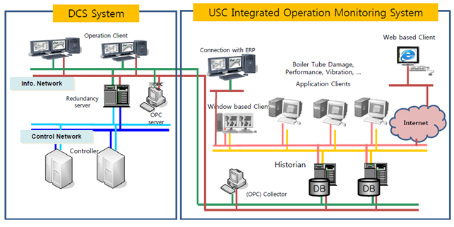
3-1 Structure and Features of Taichung No. 5 ~ 8 Boiler Monitoring and Diagnostic Platform
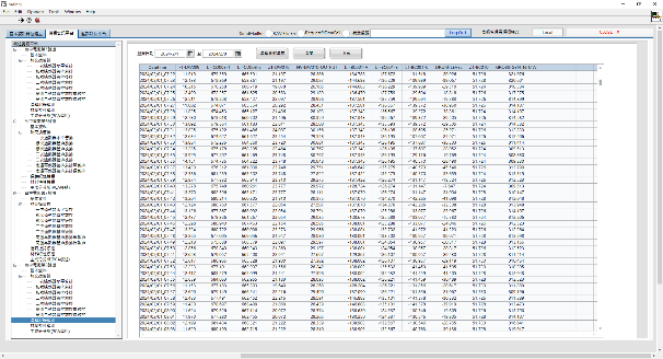
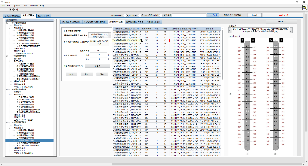
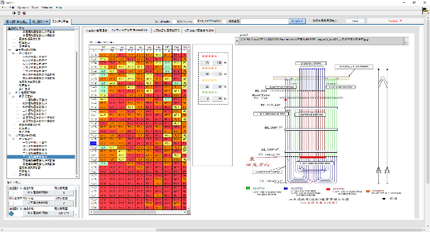
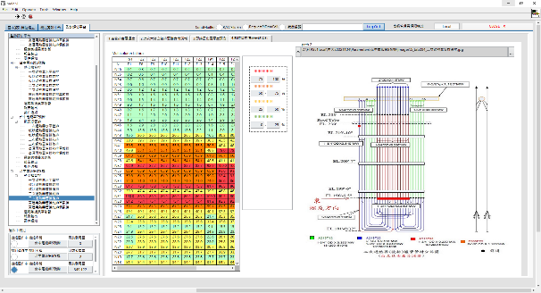
The real-time operation data is transmitted to the Pi server for storage through the No. 5 ~ 8 DCDAS system, and the Pi server transmits the real-time operation data to the No. 5 ~ 8 online monitoring and diagnostic platform for storage and calculation. Colleagues refer the analysis results of the platform. The main features are as follows:
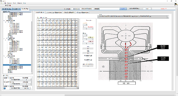
- Access the real-time operation data of Pi Server to the monitoring and diagnostic platform for analysis and calculation. Evaluate the difference between the each metal temperature of tube bundle on creep deterioration trend. Observe the creep deterioration effect of high-temperature and high-pressure long term operation on the tube bundle.
- Through the overhaul report of the oxide layer measurement data, evaluate the influence of the tube deterioration in the past two years of operation. Taipower observe where the tube bundle weaknesses are.
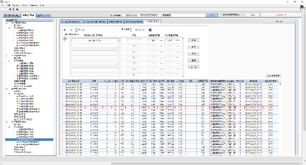
- Monitor boiler feedwater consumption and hotwell level changes by analyzing daily operation data. Observe the signals of short-term tube leakage and expect to make a notice.
- Self-developed coding and planning monitoring and diagnostic platform to build up research capacity.
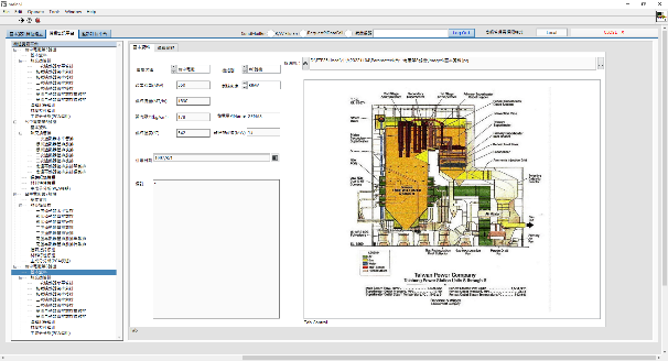
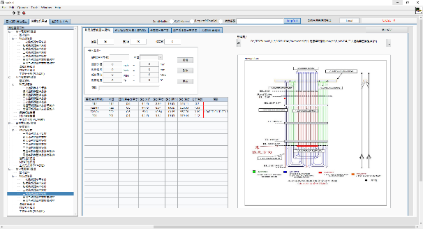
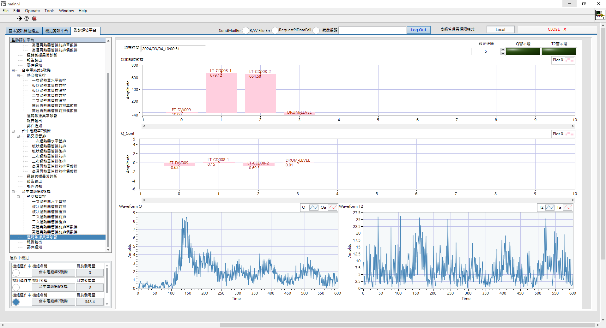
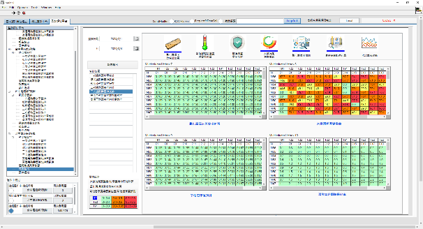
3-2 Interface of Monitoring and Diagnostic Platform
The system flow chart and function interface are shown in the figure below:
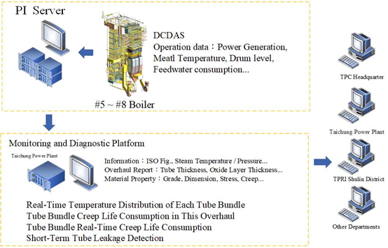
System Structure
4. Achievements and Prospects
Taipower built monitoring and diagnostic platform for the Taichung No. 5 ~ 8 boiler. Conducting the annual overhaul report and the real-time operation data, monitor and observe the creep damage and feedwater trend of the tube bundle under high temperature and high pressure operation for a long time. System can detect the possibility of tube leakage to reduce the probability of unexpected shutdown and promote the reliability of power supply.
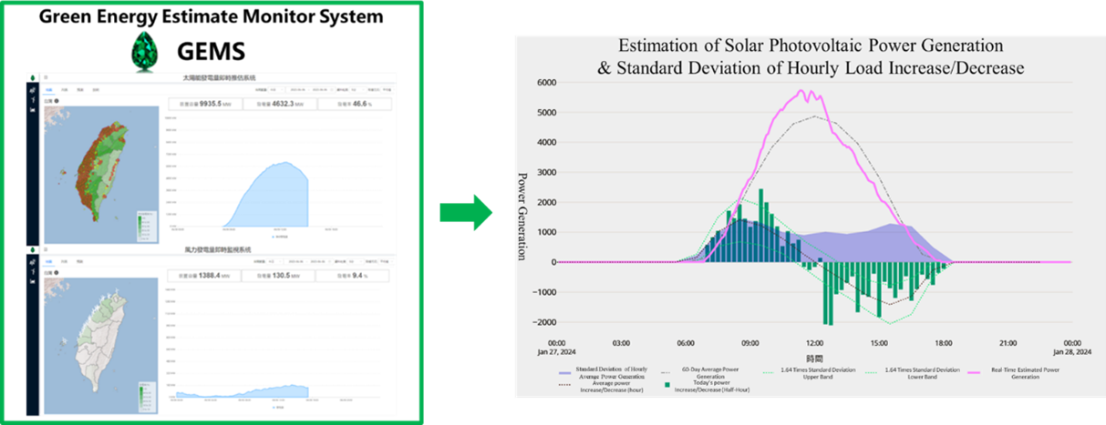
Green Energy Estimate Monitor System (GEMS)
Taiwan has a maritime island climate, characterized by distinct seasons and frequent afternoon thunderstorms. These weather patterns significantly impact solar photovoltaic (PV) power generation. To quickly detect deviations between actual PV power output and predicted values, visualizations are essential.
Therefore, on the existing Green Energy Estimate Monitor System (GEMS), a new solar photovoltaic standard deviation feature has been developed. It incorporates the concept of standard deviation mathematical models and utilizes historical and current solar photovoltaic generation data. The system calculates the average hourly power generation and the hourly variation in power generation (as indicated by the gray and black dashed lines in the diagram). It then presents the variation by adding or subtracting 1.64 times the standard deviation to create upper and lower trajectories (shown as light green dashed lines). Additionally, the standard deviation of historical hourly power generation variations (represented by the light blue area) is displayed as the range interval. The ramp of power generation every half hour on the monitoring day (that day) is normalized (multiplied by 2) to hourly, and the current situation is displayed quickly through real-time display (green bar).
Analyzing the standard deviation of each period through historical data of different days, the results suggested that 60 days is better. Calculated based on the changes in photovoltaic power generation for each hour in the past 60 days, there is a 90% chance that photovoltaic ramp of power generation for each hour of the day within the upper and lower trajectory of the standard deviation. It can be used as a reference for preparing Fast Responsive Reserve units to prepare Fast Responsive Reserve Units in advance to cope with the impact of photovoltaic power generation by seasonal changes.
The Building and Application of IEC 61850
1. The building of IEC 61850
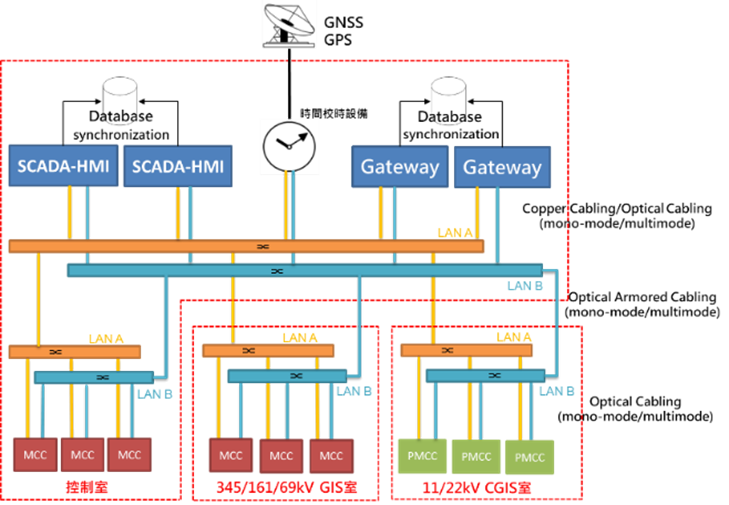
At present, nearly 90% of the substation automation monitoring architecture adopt remote terminal units (RTUs), and most of the power meters, IEDs and RTUs use communication protocol DNP3.0. The monitoring architecture of the other substations adopt Local SCADA and gateway. The communication protocols between the gateways and IEDs are different (Modbus, DNP, LON, Profibus, etc.). The main function of these two substation automation methods is updating the real-time operation information in substation to the control center for dispatching (vertical communication), while the information cannot be exchanged horizontally between substations.
The full name of the IEC 61850 standard is “Communication networks and systems for power utility automation.” The latest version, Edition 2, is an internationally accepted power automation standard that conforms to the future development trend of smart grids. Its main purpose is to provide the interoperability between different brands of IEDs.
In addition, the substation automation following the IEC 61850 monitoring architecture is also beneficial for the improvement of the reliability of power supply. This architecture provides a platform for horizontal communication (GOOSE) of automated equipment in the substation, enabling various equipment that enables to complete the application scenario of protection and operation in power system.
2. GOOSE Application of Simultaneous Accidents between Two Feeder Lines in compliant with IEC61850 Substation
A. Abstract
The application of smart grids in the field of power transmission and transformation is mainly on the construction of substation automation based on the internationally accepted IEC 61850 standard. Intelligent electronic devices (IED) are the basic elements of digital automation substations, providing the protection, measurement, control and communication functions required by the system, and the GOOSE function which transmit events fast is used to transmit important instantaneous command signals between multiple IEDs. For this reason, the digital network communication is the substitute for the hard-wired control loop between traditional devices to achieve IEDs interoperability. In order to solve the problem of protection coordination difficulty caused by the simultaneous failure of the common feeders, which caused cross-zone tripping, the GOOSE information can be used to detect the IED trip protection logic to speed up feeder tripping, which strengthen the protection coordination between upstream IEDs and downstream IEDs, speed up the IED tripping on fault feeder to isolate the fault and reduce the scope of power failure.
B. Construction
Taking the 11.95kV BUS devices in the following figure as an example, there are MCB, CB1, CB2, CB3, and CB4, five circuit breakers. Among them, the CB1, CB2, CB3, and CB4 are feeder circuit breakers, and their IEDs planning GOOSE command accelerates CB tripping.
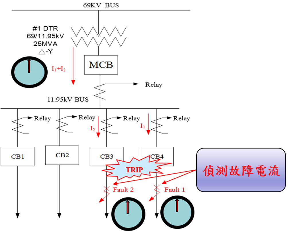
- Logical summary description:
When any two feeders have a fault current at the same time, the two feeders will speed up immediately after judging the 6-cycle stable delay (you don’t need to wait for the 51 / 51N relay delay-end and tripping). It can avoid simultaneous failure of the two feeders’ fault current smaller than the fault situation of a single feeder that makes 51 / 51N relay take a long time to operate, which causes the MCB’s 51 / 51N action to trip. The relevant logic plan is as follows:
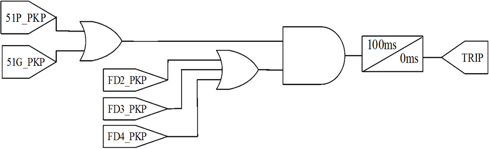
GOOSE publisher:
FD1_PKP=51P_PKP OR 51G_PKP
GOOSE subscriber:
FD2_PKP,FD3_PKP,FD4_PKP
- Accelerated trip logic:
Once a fault occurs on the CB1 feeder, when the 51 / 51N relay pickup and the IED have received the pickup Goose signal from other feeders in the same bank, if more than two feeders fail at the same time, a large current will be generated in MAIN, causing MAIN’s IED to start tripping, causing incorrect trips and expanding power outages.
In order to prevent this phenomenon, when two or more feeders fail at the same time, we use the GOOSE on the IEDs of each feeder to transfer the PKP to each IED on faulted feeder, determining that when the two feeders fail at the same time should be delayed and tripping after 6 cycles to prevent MAIN CB tripping due to large currents first, causing a power outage on the sound feeder.
C. Benefit analysis
When more than two feeders have fault occurred at the same time, we accelerate the accidental feeder trip to avoid the action of the main circuit breaker, reducing the scope of power outages and improve the efficiency of power supply.
A Big Data Analysis System and Management Platform for Circuit Breaker Operation Timing
1. Abstract
In 2014, Taipower began using Intelligent Electronic Device (IED) operation information from Remote Terminal Units (RTU) and IEC 61850 substations as trigger signals for calculating the Sequence of Events (SOE) times for auxiliary switches from circuit breakers. An online circuit breaker inquiry system was then established, and more than 830,000 pieces of information have been accumulated so far. In 2018, AI big data analysis was introduced using equipment brand, age of use and past operation timing. This led to the successful diagnosis of 410 abnormal circuit breakers, particularly those with dull or delayed mechanisms. The prediction accuracy rate reached 30%.
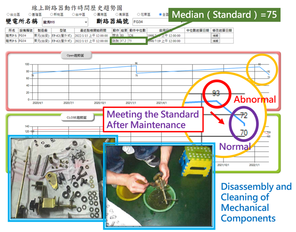
In 2021, the median number of the close/open operation timing was used as the diagnostic standard and the construction of IEC61850 standard substations was promoted. This will effectively improve accuracy by 40% and result in the successful diagnosis of 70% more abnormal circuit breakers.
To allow for ongoing status monitoring, a web-based management platform and an notification app were developed. When a circuit breaker experiences an abnormal operation, the system will immediately notify maintenance personnel so that the issue can be resolved quickly. This greatly improves the security of the power grid.
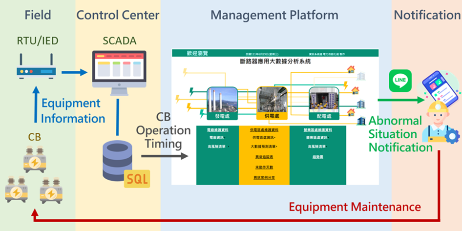
2. Big Data Statistical Analysis of Online Circuit Breaker Operation Timing
The operating times for circuit breaker that was obtained through the RTU/IED triggered SOE information technology (see above) varies depending on the sampling circuit and the auxiliary switch of the operating link. According to analysis, performed using the AI big data XGBOOST model, under normal circumstances the close/open operation timing is less than 5ms regardless of whether the circuit breaker is closed or open. Consequently, the median number of the close/open operation timing was introduced in 2021 as the diagnostic standard, allowing for greatly shortened AI big data analysis times.
3. Construction management platform and practical application results
The large database of circuit breaker operation times was combined with data management functions to build a management platform. This platform allows for the reporting of abnormalities in real-time and issues notifications via app. This quickly alerts maintenance personnel and appraises them of the situation so that maintenance can quickly be arranged in accordance with the problematic equipment’s operational trends, brand, type and use history. At the time of writing, 223 circuit breakers with institutional exception have been diagnosed and processed.
Transformer Condition Monitoring
Base on power supply dispatch’s substation maintenance manual, TPRI’s oil test will be done every year unless fault or abnormal situation of transformer happens. It is impossible to know the internal fault situation of the transformer in advance if we cannot obtain the gas content of the oil in the transformer and the operating status of the equipment timely. Current DGA(Dissolved gas analysis, DGA) shows the total amount of gas, it is hard to know exactly the amount of each gas, and the high number of abnormalities and expensive maintenance makes it not economical.
To ensure operation safety and achieve preventive maintenance, Taipower planned to install DGA for power supply units and replace the existing combustible gas detection device from the total type to the component type. It can obtain the content of gas components (H2, CO, water content) in the oil and alarm information, and judge the health of the internal operation of the transformer through each gas trend chart as the basis for CBM. It is expected that the effectiveness of the staff can be increase, equipment failure and blackout time can be decrease and ensure stable power supply.
Besides DGA, planning of existing transformer oil gas monitoring, transformer equipment asset management, and artificial intelligence AI applied to the transformer operation and maintenance strategy expert system for horizontal information integration and database interface to further master the transformer operation situation. If the abnormal situation of transformer is analyzed correctly, power outage maintenance can be arranged in time to avoid unforeseen power outages caused by accident.
Replacing Transmission Towers with a Novel “Tower Wrapping replacement Method”
1. Abstract
Transmission towers are a vital element of the transmission system. However, natural environmental factors, such as wind and sun exposure, gradually corrode and damage tower structures over the years. Consequently, towers must periodically be replaced.
Old transmission towers are typically replaced in one of two common ways. In the first method, power is turned off in all transmission lines on the old tower. Lines are then switched to the new tower one by one. Unfortunately, this “power outage method” reduces system scheduling flexibility and increases operating risks. In the second method, temporary poles and lines are erected. This method requires additional land to accommodate temporary poles. It may be more difficult in some areas with poor land.
The “tower wrapping replacement method” proposed in this article solves the difficulties associated with both conventional replacement methods. It not only avoids the simultaneous power outage of transmission lines but can also be applied flexibly to any location. This method enables the power transmission system to accomplish the replacement of old transmission towers with the lowest possible impact.
2. Introduction to the Tower Wrapping Replacement Method
As the name suggests, the tower wrapping replacement method, installs the new tower around the outer side of the old transmission tower and gradually replaces it. The method entails the following steps (also outlined in Figure 1):
- First, install new tower angle irons on the existing foundation of the old tower. Next, set up the new tower footings on the new angle irons. When power is turned off on the left side of the old tower, the left side of the new tower’s body is installed.
- When power is restored to the left side of the old tower, power to the right side can be turned off. The right side of the new tower’s body can then be installed. Additionally, power lines can be moved to the right side of the new tower. Once the lines have been shifted, the old cross-arm can be removed from the right-side of the old tower.
- A new cross-arm can be installed on the right-side of the tower. Wires can then be moved to the new cross arm.
- When power is restored to the lines on the right-side of the tower, the power can again be cut to the left side of the tower. The lines from the old, left cross-arm can then be moved to the left-side of the tower body. After the lines are shifted, the old cross-arm can be removed from the left-side of the tower.
- The new cross-arm can then be installed on the tower’s left side and power lines can be moved onto it.
- Finally, the body of the old tower can be removed and power can be restored to the left-side of the new tower. This completes the replacement process.
3. Advantages and Prospects:
The greatest advantage of the Tower Wrapping Replacement Method, proposed here, is that it does not involve either simultaneous outages or land acquisition. During the replacement process, power lines on at least one side of the tower can maintain a continuous power supply. These features allow this method to greatly alleviate the above-mentioned difficulties while loosening the time and space constraints on the replacement of old transmission towers, thereby increasing the flexibility of maintenance work.
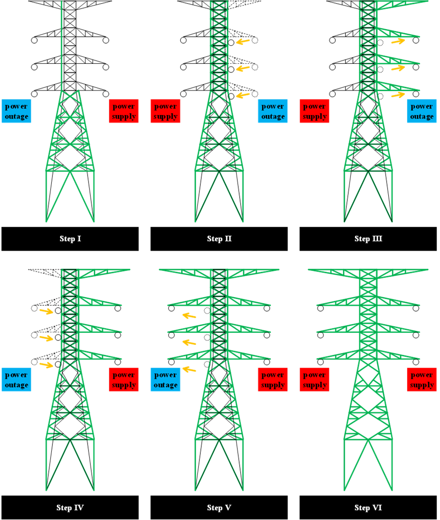
Figure 1 – The Tower Wrapping Replacement Method
Study for the feasibility of establishing early warning system disaster management with the real-time kinematic(RTK) in power supply units
1. Abstract
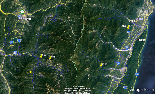
Taiwan is located on the Pacific Rim earthquake belt and the path of typhoons in summer. Therefore, natural disasters such as earthquakes and typhoons often occur. The mountain slopes are steep with rapid currents and the geology is fragile, causing natural disasters such as slope collapse, earth and rock flows, endanger the safety of transmission towers in mountainous areas. In response to the problem of power supply stability due to the sliding of tower foundation slopes by the extreme weather in recent years, the project applies fixed-type tilt meter and other slope monitoring instruments with real-time dynamic positioning system to 5 towers, including 345 kV Daguan, Mingtan - Fenglin line , #52, #68, #163, and 161 kV Fenglin Hualien Line # 76, # 77, for the construction of the tower-based slope disaster prevention early warning system and the application of real-time dynamic positioning assessment research. This project is to monitor target towers with the real-time kinematic, structural monitoring system, tower-based monitoring system and environmental monitoring system. The back-end management system provides an early warning function, and the warning signals of the monitoring equipment are displayed with lights in the tower-based monitoring management platform, so that tower maintenance managers access to cloud data through the user monitoring interface, and immediately grasp the status of the monitoring tower.
2. Method
The basic dynamic intelligent monitoring system of the tower includes four systems: power system, sensing system, communication system and data system analysis management. Taipower plan to use real-time kinematic, structure monitoring system, tower-based monitoring system and environmental monitoring system to formulate the sensing system for monitoring the target tower. The functions of each system are summarized as follows:
The real-time kinematic is based on high-precision 3D positioning data obtained from two GPS stations and one GPS fixed station set up around a single tower to monitor the long-term trend of the site of the tower.
The structure monitoring system is designed to understand the structural behavior and rigidity of the tower by means of the acceleration gauge, strain gauge and tilt meter set up in the base of the tower.
The tower-based monitoring system is set tiltmeter on the basis of the tower base to measure the change of the tower-based tilt and automatically measures the sliding deformation of the stratum by setting a fixed tiltmeter for comprehensively safety evaluation.
The environmental monitoring system provides early warning for geo-slip analysis and slope-land disasters by using rain gauges, water pressure meters, anemometers and wind gauges to understand rainfall, wind speed, wind direction and monitoring of groundwater level changes.
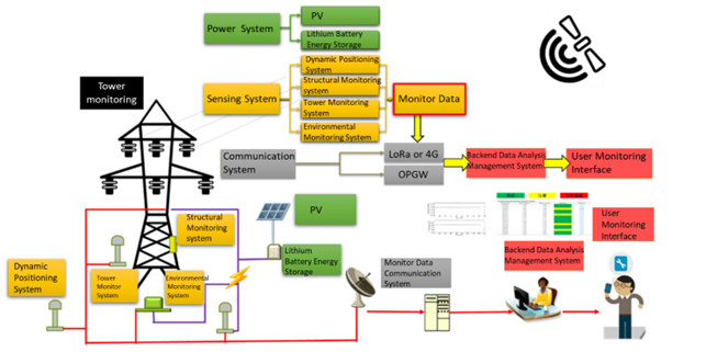
In addition, the sensing system require the power system to provide the power. This project uses the solar power generation system to supply the overall monitoring system power source, and establishes a stable power supply system, including lithium battery energy storage equipment, so that when the power is insufficient, the energy storage equipment can supply the power for communication at least 30 days. Monitoring data is transmitted through the communication system to the management platform. This project is evaluated to use reliable communication technology for the monitoring tower to the connection tower (with Taipower OPGW Joint Box tower) such as LoRa, 4G… and build its communication system, and carry out the communication test of photoelectric conversion.
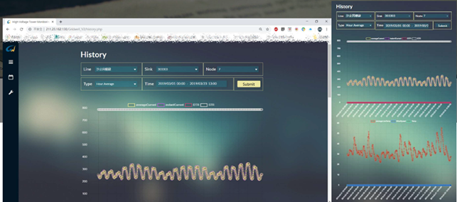
The data analysis management system is the processing center for all monitoring data. Taipower can get complete and long-term monitoring data, real-time monitoring of geodetic displacement, structural displacement, and water level observation, and analyze whether relevant real-time data exceeds the safety alert value. This system will provide an early warning after data is analyzed. The warning signal of the monitoring equipment is displayed on the tower-based monitoring and management platform, so that the field personnel can obtain cloud data through the user monitoring interface, and immediately grasp the status of the monitoring tower.
3. Projects objectives and benefits
The objective of this project is to establish a long-term monitoring system for the target tower, to grasp the structure of the tower and the situation and development of land shift, and to provide reference for the maintenance, power operation and disaster early warning. Accordingly, the project intends to carry out the construction of local power systems, communication systems, monitoring instruments, and the development of monitoring webpages for 5 monitoring towers, with the following objectives:
- Establishment of sensing systems real-time kinematic, structure monitoring, tower-based monitoring, environmental monitoring).
- Establish a power system (solar power generation, lithium battery storage equipment).
- Establish communication system (LORA, OPGW).
- Establish a monitoring data management system.
- Develop a follow-up proposal for improvement and a suitable tower monitoring system for Taiwan Power Corporation.
This project envisages the establishment of the basic dynamic intelligent monitoring system of the tower and achieves the following results.
- Establish an independent power supply system to solve the power supply problem of the tower monitoring equipment.
- Establish an intelligent monitoring system to assist the inspection, maintenance and management of the tower.
- The monitoring numerical big data database of geological environment and structural security of the domestic tower is established to provide the alert analysis of the back-end platform.
- Establish the domestic tower contingency decision-making process to improve the stability and reliability of existing power supply system.
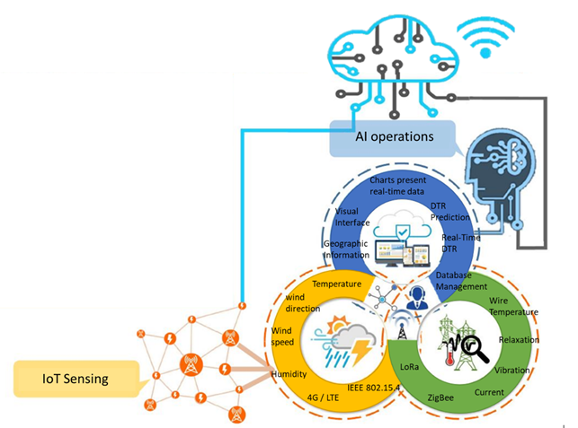
Research on the Advancement and Integration of Dynamic Thermal Rating System
1. Abstract
In order to realize the smart transmission plan, this project investigate the method of increasing the transmission capacity. According to the power associations in the world, including the IEEE, JCS, and CIGRE, the relevant standards are formulated based on heat equation of conductor. The dynamic thermal rating (DTR) method is proposed to effectively increase the transmission capacity with real-time data. The project studied DTR according to the plan requirement. The contents before the first mid-term report have five points. 1. Compare and explore DTR and static thermal rating (STR). 2. Discuss DTR formula and parameter. 3. Collect relevant DRT research and application of foreign electric industry and manufacturers. 4. Design and Verify IoT technology introduced into high voltage system. 5.Design and verify DTR equipment.
This study is a practical application of DTR. In addition to data collection, performing high-voltage and high-current tests are also necessary on DTR equipment to test and prove the reliability and stability of the equipment, which is conducive to subsequent research in the line installation under the supervision of operators and equipment. This will help to understand the actual state of the line after capacity increase and accumulate the experience of using DTR to improve capacity operation. In the future, it can further modify the power dispatching and power transmission specification.
2. Content and method
Dynamic thermal rating equipment and small weather stations with wireless communication testing and verification
I. High-pressure testing and verification
II. High current testing and verification
III. Lightning surge test and verification
IV. Wind tunnel test, withstand 17-level gusts or more
V. Installation of equipmentApplication management platform program development
I. Web design future energy boundary “transmission equipment maintenance management system”
II. Responsive Web Design (RWD)
III. Ground management interface
3. Target
In order to realize the dynamic thermal rating monitoring, this plan will investigate the current application status of dynamic thermal rating or related equipment on the market in order to understand the relevant results of foreign dynamic thermal rating research as a reference for this research. The plan uses domestic existing dynamic thermal rating monitoring equipment, installed on Taipower’s designated transmission line, and installs a small weather station to collect real-time weather information around the tower to collect real-time and accurate power line dynamic heat capacity information. Through big data and Application of artificial intelligence technology, analyze and discuss the prediction technology of dynamic heat capacity. At the same time, this plan also intends to build a dynamic heat capacity cloud application management platform to display the power line environment information and dynamic heat capacity information in real time to provide more information for maintenance personnel to judge the safety of power lines.