The monitoring and control of the smart grid are a variety of operational and energy measures including smart meters, smart appliances, renewable energy sources, and energy efficiency resources that are with the computer-controlled applications.
In response to the policy of energy transition in Taiwan, a great amount of renewable energy will be installed in the future. To reduce the impacts of the distribution energy resources, Taiwan Power Company (TPC) is improving its monitoring and control system at each control centers and is developing applications such as Green Energy Estimate Monitor System (GEMS) and Distribution Renewable Energy Advanced Management System (DREAMS) to solve the uncertainty of renewable energy and to maintain the power system quality.
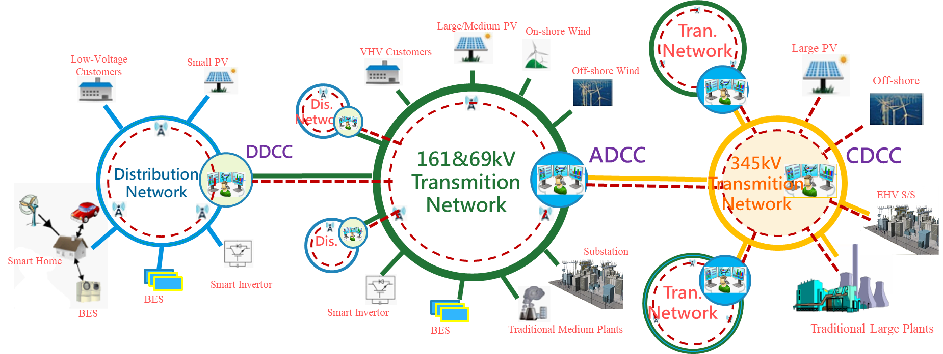
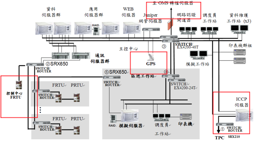
Figure 1.1 TPC Network Architecture
Introduction of Monitoring and Control Structure
TPC aims to provide secure, reliable, and high-quality power through a three-tier Hierarchical Dispatching Control Structure as shown in the figure below that includes Central, Area, and Distribution Dispatch Control Center (CDCC/ADCC/DDCC). The three-tier centers a responsible for the generations and trunk networks (i.e., 345kV and 161kV tie line among ADCCs), the 161/69kV networks, and the 22.8/11.4kV distribution systems, respectively.
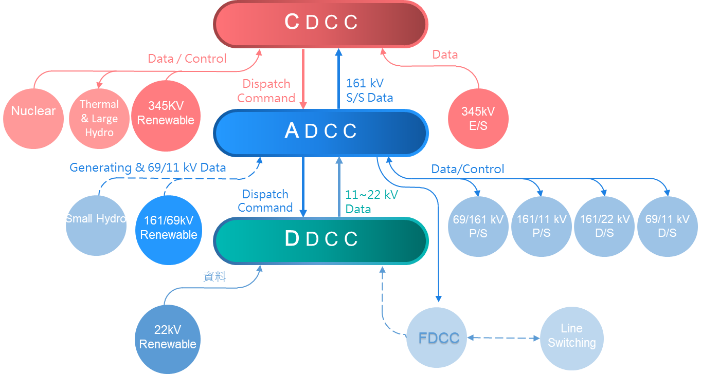
Figure 1.2 The three-tier centers of TPC
Central Dispatch Control Center (CDCC), the core of TPC’s system generation dispatching and network control, is the center of the national electricity supply operations. The tasks of the CDCC are to operate the national power generation and the transmission grid of the whole country, including water resources coordination, thermal (coal, oil, and natural gas) and nuclear power plants dispatching, and the EHV substations and network control.
The operators in CDCC are on duty 24-hours a day to monitor the system operating status, meet the power demands, and maintain the stability and security of the power system.
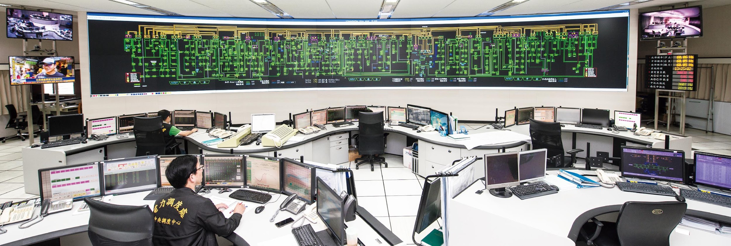
Figure 2.1 The CDCC of TPC
Dual-Master Synchronous Operation Scheme (DMSOS)
The Energy Management System (EMS) was first installed at the CDCC of TPC in 1980 and replaced by a second-generation system in 1990. Several factors led to the deployment of a backup CDCC, including a large earthquake in 1999, the September 11th terrorist attack in the United States, SARS, and H1N1 natural disasters. Since then, TPC has updated the EMS of CDCC in Taipei (TCDCC) and deployed a full copy of the EMS and control center in Kaohsiung (KCDCC). However, with the increased need for operators and advanced multi-site functions of EMS, TPC finally decided to set up equal personnel on both sites.
In response to these events, KCDCC now plays not only the backup role but also as a peer-to-peer control center that corresponds to TCDCC. This means that in addition to the facilities matching, the operators are also identical on both sites. When one site stops functioning, the other can immediately take over all real-time tasks to ensure no disruption in system operations. This new third-generation EMS with dual control centers was completed on July 10th, 2009. After refining various functions of the new EMS and the supplement of the staff, especially operators in K -site, a Dual-Master Synchronous Operation Scheme (DMSOS) has been successfully operating in the TPC system.
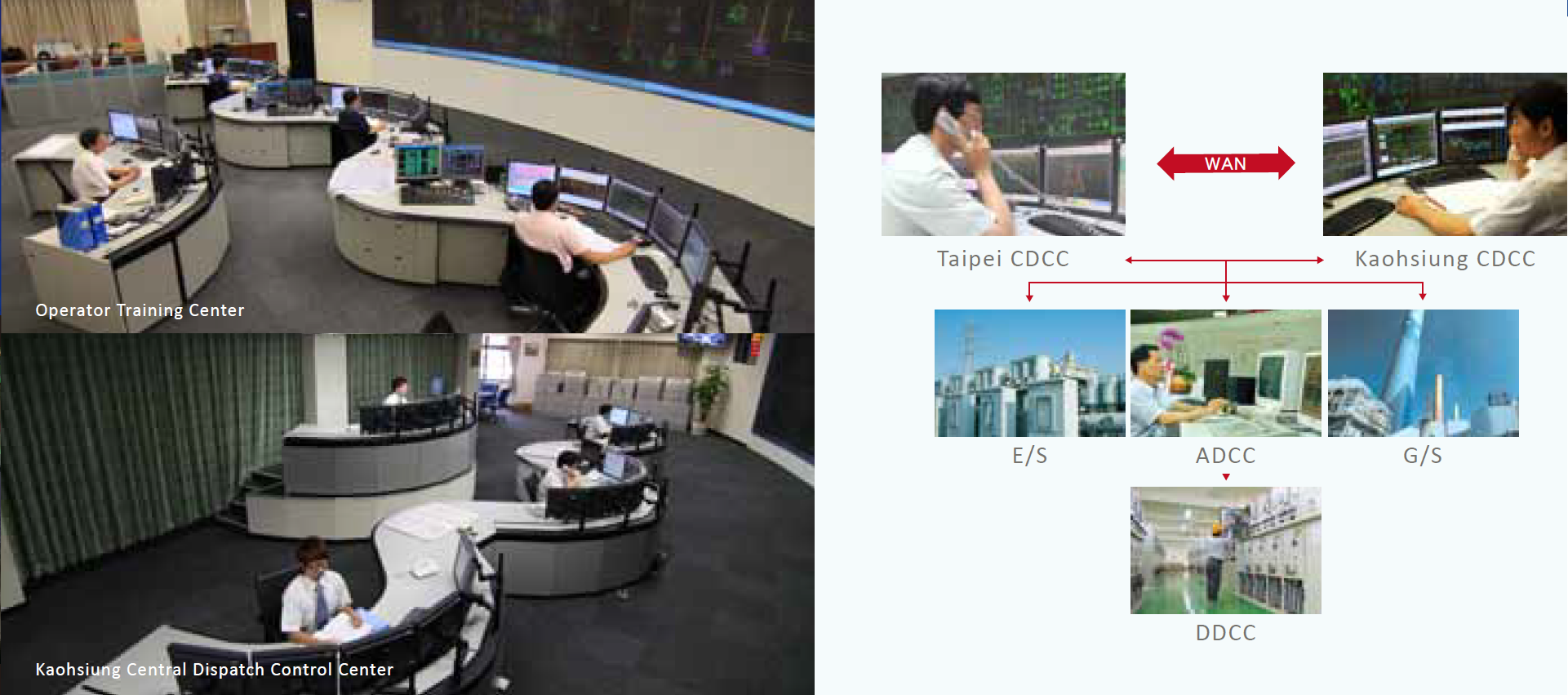
Figure 2.2 The DMSOS of TPC
Hardware Configuration
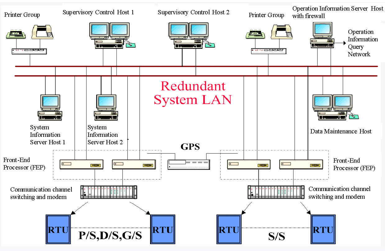
With DMSOS operations, open protocols and distributed systems platform architecture is used to build a computer system that can operate in Taipei or Kaohsiung site independently. The two sites are connected to each other via three independent routes of high-bandwidth WAN, including two fiber-optic SDH (synchronous digital hierarchy) backbones (50Mx2) and one microwave channel (7xT1, 10M) to ensure the reliability of SCADA data exchange and synchronization.
The data collected from the RTU/ICCP of power plants, extra-high voltage (EHV) substation, and ADCC are sent to the two sites simultaneously, while in normal conditions just one site, named DRCC (Data Responsibility Control Center), to receive and exchange synchronously so that the operators in two sites could see the same real-time information and operate the power system either independently, or merged as a single virtual center.
Besides, based on the remote function of EMS and with a dedicated WAN, two emergency remote control centers are installed in case of operators could not enter the main control center for any reason and could dispatch the power system remotely.
Software Applications
The EMS is equipped with a complete set of the most advanced applications for power system operation planning. It consists of the supervisory control and data acquisition (SCADA), power application (PA), network application (NA), and scheduling application (SA).
Automatic generation control (AGC), the main function of PA, can be transferred to any site at any time and supports the capability to simultaneously handle multiple control areas caused by network islanding. Economic dispatch (ED) allocates the generating demands among the committed units to minimize operating costs. For NA, besides the state estimation (SE) combined with fault current calculation (FC) and contingency/security analysis (CA/SA) for steady-state vulnerability assessment. Unit commitment (UC), the main function of SA, determines the schedules for thermal generating units while minimizing the total operational cost, and satisfying system load requirements and operating constraints over the study periods. With the advanced applications and equipment, the EMS takes into account real-time system security surveillance to improve the power supply quality and reduce operating costs.
Operators not only use the EMS to dispatch the power system, in addition, Power System Facility Maintenance Management System (PMS), Phasor Measurement Units (PMU), Lightning Location Detection System (LLDS), and Quantitative Precipitation Estimation and Segregation Using Multiple Sensor (QPESUMS) are also introduced to provide the information needed for the dispatching strategic judgments.
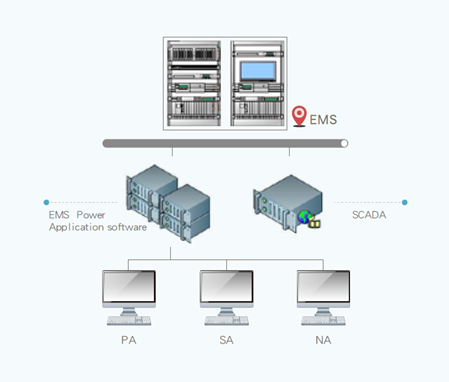
Figure 2.3 EMS Software Applications
Software Applications
With the new advanced EMS schemes and functions implemented in CDCC, a Dual-Master Synchronous Operation Scheme (DMSOS) has been successfully operating in two-site control centers and is identical not only at the EMS facilities but also in operation staffs. Operators under DMSOS are able to monitor and control the system in a more reliable, stable, safe and efficient manner. We anticipate that the reliable service of the TPC system will be greatly enhanced and the probability of blackouts due to natural disasters and attacks could be minimized. We believe that this novel operation scheme is the first system operated in the world and will become a model for future power system control center design and operations. Power system operations in TPC are now facing many challenges, such as the implementation of the smart grid, the development of renewable energy, the capacity increase of wind power, solar energy, and natural gas units, the impact of the greenhouse issue, the measurement of compound disasters, the competition from private power plants, and the deregulation and liberalization of the power market. Nevertheless, we have confidence that these issues will be well managed in the future.
Taiwan Power Company (TPC) Area Dispatch Control System (ADCS) are currently using a hybrid of SCADA solutions across its 6 Control Centres in Taiwan. ADCS SCADA systems monitor and/or control the following substations: Extra High Voltage substations(345/161kV), Primary Substations (161/69kV), Distribution Substations(161/22/11kV) and Secondary Substations(69/11kV). Besides SCADA, ADCS also runs Volt/Var control to maintain and/or improve the power factor and regulates bus voltage in substations.
TPC plans to reduce the number of control systems from 6 to 5, namely New Taipei ADCS (combining Keelung and Taipei ADCS), Hsinchu ADCS, Taichung ADCS, Hsinying ADCS and Kaohsiung ADCS. Each Control System will have their respective hot backup system. State-of-the-art features such as Historical Information Server, Multisite, Reactive Power Device Control, Common Information Model, Cyber Security enforcement and development platform will also be included.
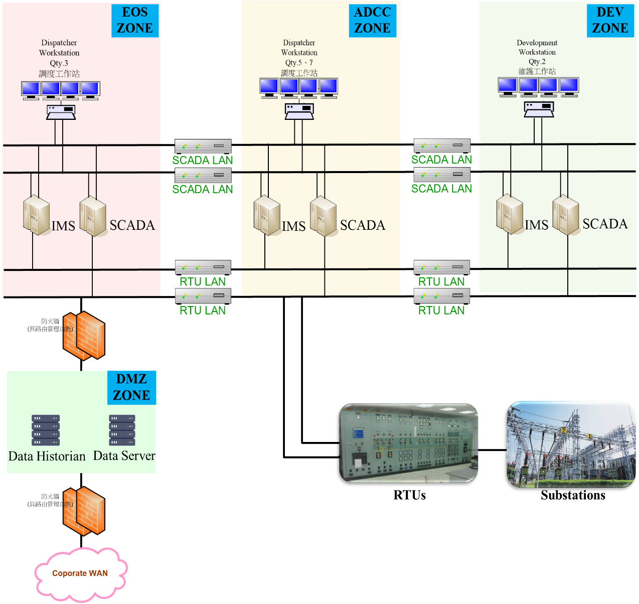
Figure 3.1 ADCS’s Architecture
The functions of ADCS in the future are listed the following:
-
The dynamic display for monitor and control such as Geographic Information System (GIS) is included.
-
Provide the space that complied with IEC 61970 Common Information Model (CIM) to save historical grid operation information for mor than 10 years.
-
The reports in tabular in-build could be modified according to the operator needs.
-
Support SMS function that the message can be check before sending.
-
The scheme of control in RPDC can be satisfying to the necessary for system reliability.
-
Provide Remote backup solution to protect ADCS from server failure.
-
The RTU apply DNP3.0 over Ethernet for communication to advance the reliability in data routing.
-
Provide the connection between DMZ and intranet to prevent the cyber security from hacking.
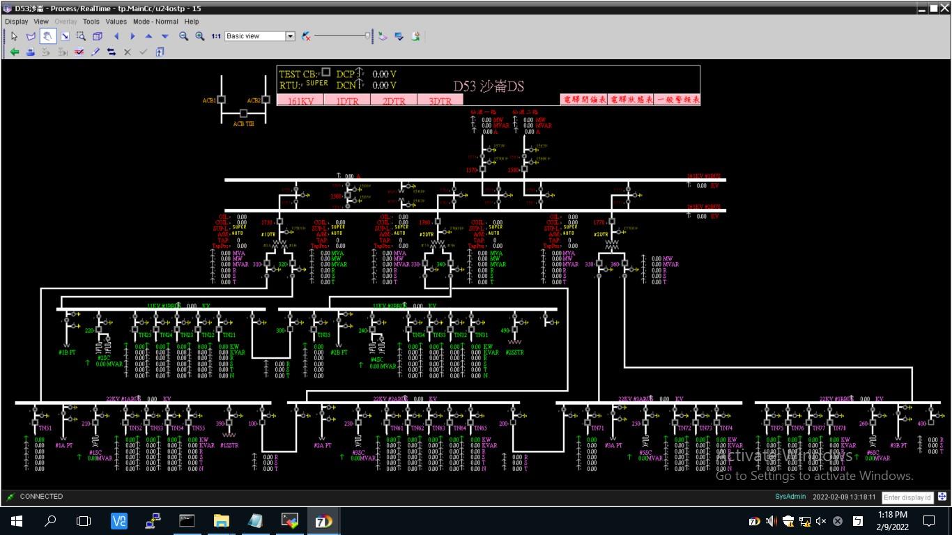
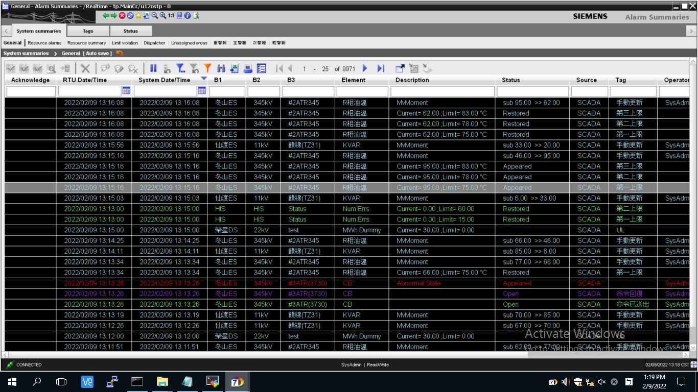
Figure 3.2 Supervisory Control And Data Acquisition (SCADA) function.
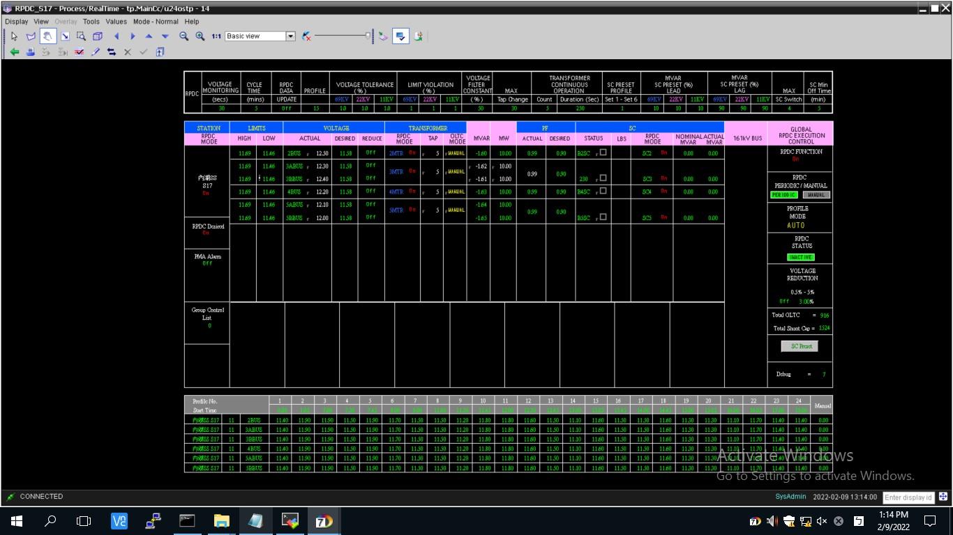
Figure 3.3 The scheme of control in RPDC can be satisfying to the necessary for system reliability.
Figure 3.4 Save historical grid operation information for more than 10 years.
4.1 Introduction of Distribution Dispatch Control System (DDCS)
Supervisory control system is a specific device capable of providing executive control and confirm whether the command is executed. Supervisory control system usually designed to collect large amounts of data, related to the operational information of the entire power system, commonly known as Supervisory Control and Data Acquisition (SCADA) System.
The comprehensive automation of power dispatch and control refers to the Hierarchical Dispatch Control System (HDCS). According to the power dispatching operation, it is divided into three levels: Central Dispatch Control System (CDCS), Area Dispatch Control System (ADCS), and Distribution Dispatch Control System (DDCS), responsible for the supervisory control and operation of 345 kV, 161/69 kV, and 22/11 kV systems. The operation and maintenance are respectively carried out by Department of System Operation, each Power Supply Branch belong to Department of Power Supply, and each Branch belong to Department of Power Distribution (totally 23 Branches).
The comprehensive automation of power dispatch and control takes the computer equipment of the dispatch control center as the core, takes the substation as the end. Information terminal equipment (Remote Terminal Unit, RTU) installed in the substation, which connected with the computer equipment of the dispatch control center through communication lines, is responsible for providing information of equipment in the substation and accepting operation command. As to achieve the comprehensive automation of supervisory control and data acquisition.
The functions of SCADA system includes: Data Acquisition, Data Processing and definition, Supervisory Control, Alarm Display and Control, Periodic Collection and Reports, Sequence-of-Event Recording, Trend, and Man-Machine Interface.
The work of the duty personnel in the Distribution Dispatch Control Center (DDCC) includes: Supervisory Control and Data Acquisition, Emergency Load Shedding and Partition Rolling Blackout, Street Lights On/Off and Lighting Management in Substations, Voltage Control, Inactive Power Device Control, Lower-Voltage Operation Control, Operation Data Query, Air Defense Intelligence and Lights Control.
4.2 Introduction of ADMS
4.2.1 Promotion and Benefits of Advanced Distribution Management System (ADMS)
The Situation of TPC promotes advanced power distribution management system (ADMS)
(1) (1) According to the description of the SMART GRID INDEX document 2.1 Monitoring & Control, Monitoring & Control is divided into three stages: SCADA, DMS, and ADMS. The ADMS functions should include on-site real-time data collection and control (SCADA), Automatic fault location, isolation and supply restoration(FLISR) and outage management system (OMS) application. Taiwan Power Company has developed various power distribution application management systems since 1992. As of the end of December 2025, it has established outage management system (OMS) and Feeders Dispatch Control System (FDCS) with functions such as SCADA, FDIR (Automatic Fault Detection, Isolation and Restoration , or called FLISR),and feeder single line diagram and GIS (geographic map information) in 24 Distribution Branches, covering 10,172 automated feeders 38,214 automatic switches included, the proportion of automated feeders has reached 100%; the whole 21 FDCS systems in operation are equipped with ADMS functions, the automatic Fault location, Isolation and Service Restoration (FLISR), described in SMART GRID INDEX file 2.1 Monitoring & Control.
(2) In response to Taiwan’s goal of 20% renewable energy in 2025 and the “Smart Grid Overall Planning Plan” in 2030, the number of downstream power recovery units will account for 90% of the total number of power restored within 5 minutes. The traditional distribution network will face the impact of renewable energy on the distribution network's stable power supply and more stringent dispatching efficiency. Therefore, it is planned to build a new generation of advanced distribution management system (ADMS) to integrate multiple operation information [such as distribution map, smart meter, solar photovoltaic, microgrid, electric vehicle, fault indicator (FCI), and distribution transformer terminal equipment (TTU)], introduce smart grid control functions, optimize distribution scheduling, reduce grid connection impact, and improve system reliability and equipment service life. In 2019, the company began to plan and design ADMS systems, and the case was awarded in January 2022. The winning bidder is the ADMS development team composed of MINSAIT ACS, Taiwan Fixed Network, and Xiangzheng Company. The construction period is 3 years and is expected to be launched by the end of 2027.
Promotion of advanced distribution management system (ADMS)
- Since 1995, TPC introduced the FDCS system software, and built it on a trial basis in North-South (Nihon Vending system) and Taichung (MINSAIT ACS system) Distribution Branch between 1995 and 2002. The two systems have been equipped with monitoring and control, data collection, and line fault detection, isolation and restoration functions and feeder schematic diagrams. During operation in the two Distribution Branch, fully obtained valuable experience and verify the feasibility and benefits of system operation.
- In order to integrate the functions of Distribution Feeder Automation, SCADA, fault detection, isolation and restoration (FDIR/FLISR) and Outage management system (OMS) providing for Distribution dispatching in each Distribution Branch, TPC decided to purchase different FDCS system in 2003 at the North-South and Kaohsiung Distribution Branch. To verify the different brand of FDCS system for the integration of SCADA, FDIR and OMS specific ways, TPC had evaluated the two brands of system through FDCS indicators by people who has experience and practical in distribution network operation. To select the suitable one for operation in Taiwan distribution network, as the distribution system operating standards in Taiwan.
- In 2007, the winning FDCS system (Siemens) that was built in Kaohsiung District was selected to promote all Distribution Branch in Taiwan. The FDCS system acceptance project was carried out in Taoyuan County, and a team composed of inter-departmental and academic staff from TPC was responsible for functional verification. At the same time, the ICP training plan (Industrial Corporation Program, ICP) was carried out, and the maintenance and operation technology was transferred to TPC. For the specific construction process of TPC FDCS system, please refer to the following Table 4-1.
In 2007, the FDCS system (Siemens) of the winning Kaohsiung Distribution Branch was selected to promote power distribution areas throughout Taiwan. The FDCS system acceptance project was carried out in Taoyuan County.
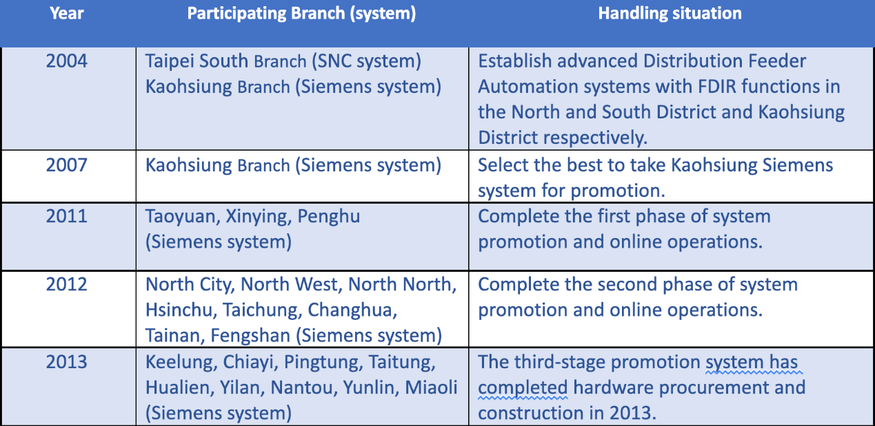
Table 4.1 TPC FDCS system establishment process
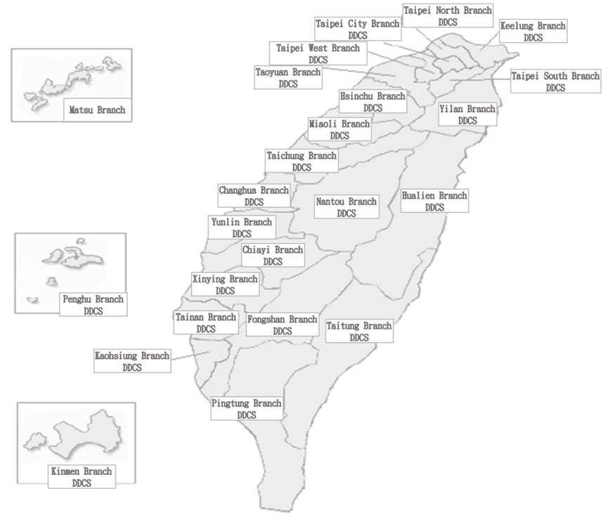
- There are currently 24 FDCS systems in operation and their distribution is shown in Figure 4-1. The system has been built successively since 2004, which can provide the ADMS functions required by Taiwan’s 22kV and 11kV power distribution feeders.
- The FDCS GIS database is updated from OMS to the FDCS system by incremental update at least twice a week. The data will be verified in OMS before the data is imported into the FDCS system, and the imported data will also be verified before launching it into the real-time database of FDCS system.
- In the 4 Distribution Branch, Taipei City, Hsinchu, Miaoli and Kaohsiung, the FDCS system monitors both the Meshed network and the Radial network. The FDCS systems in all other Distribution Branches only monitor the normally Radial network. The FDCS system can automatically perform fault detection and isolation and upstream power recovery, or provide options to be executed after the plan is confirmed by operators, and provide downstream power recovery recommended operating steps.
- FDCS system provides dispatcher training simulator (Dispatcher Training Simulator, DTS), which can be used for time-testing training of operators in daily dispatching operation exercises. All operators must test different power outage scenarios in the DTS server.
- FDCS performs local and remote backups daily and weekly to improve the reliability of the dispatch system.
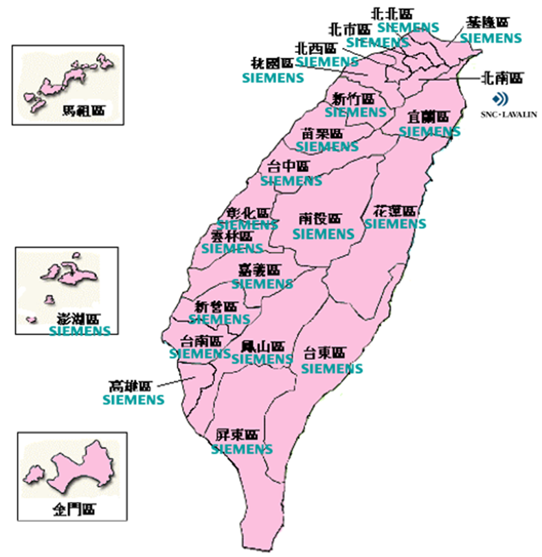
Figure 4.3 Automated system build distribution map
Existing system architecture
The FDCS system is applied to the power distribution system 11.4kV and 22.8kV overhead and underground Radial network distribution feeders. The feeder dispatching control center’s servers monitor the operation of the distribution line through the communication system and the feeder information terminal equipment. When the line fault occurs, it can quickly and automatically isolate the line fault section, automatically restore the power supply of the line's sound section, and provide GIS map information for the dispatcher and the on-site repair personnel to the area affected by the accident.
Existing system Function Description
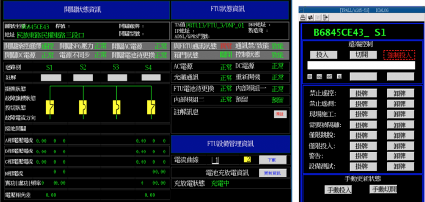
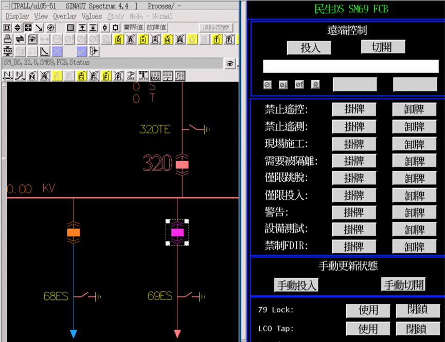
- Control center: It mainly provides SCADA+FDIR functions, and has geographic map data (GIS) processing capabilities, providing operators with complete operation screens and dispatching information; and when an accident occurs, it can assist operators to quickly restore upstream and downstream sound sections to restore power. The expansion capacity provided by the system allows feeders and substations in the whole district to be included in the scope of Distribution Feeder Automation.
- Field equipment: It can monitor various substation information terminal equipment (FRTU), feeder information terminal equipment (FTU) and other equipment installed on Radial network means or Meshed network.
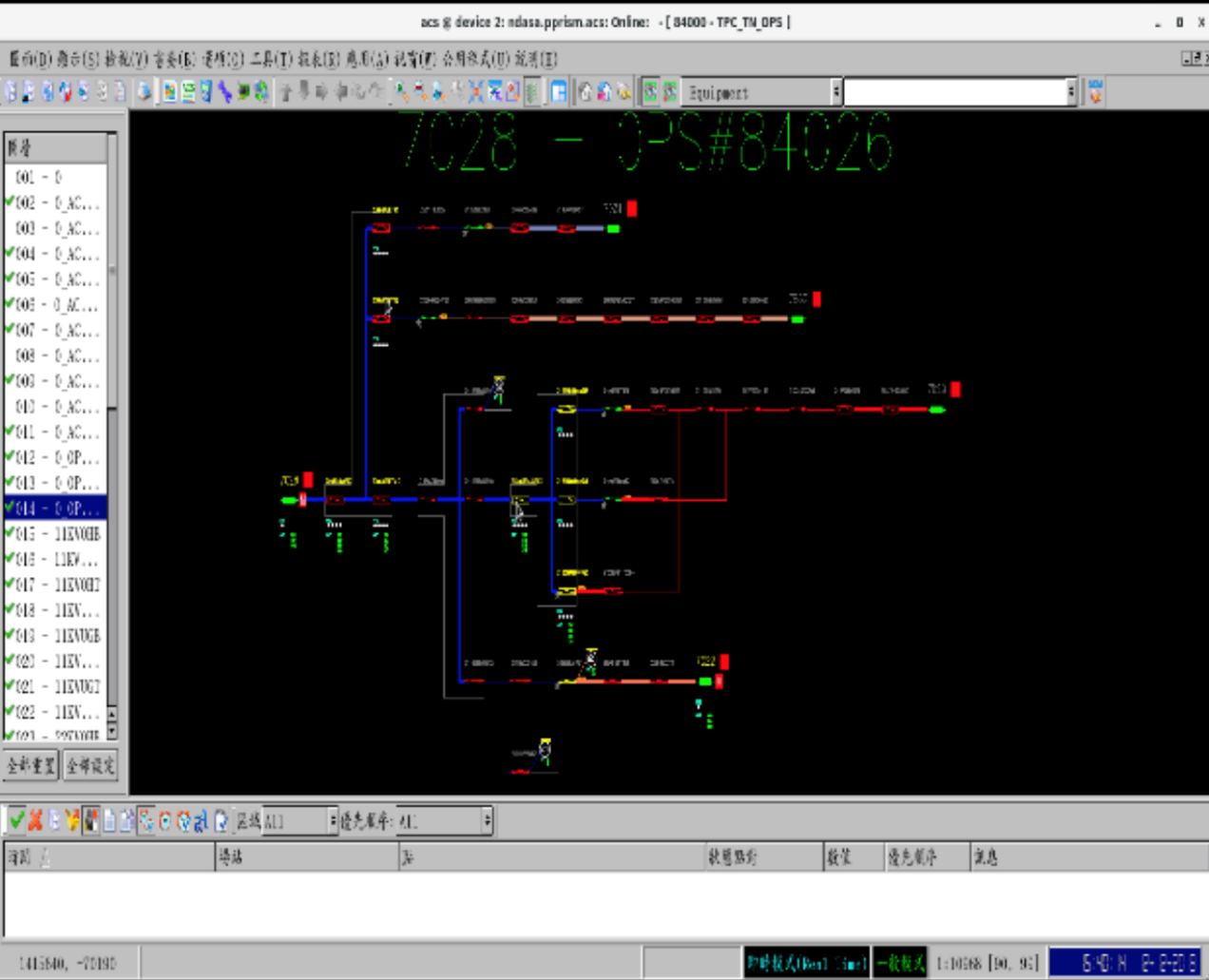
Supervisory Control And Data Acquisition (SCADA) function
- Monitor and control of automated switches, and devices within substation
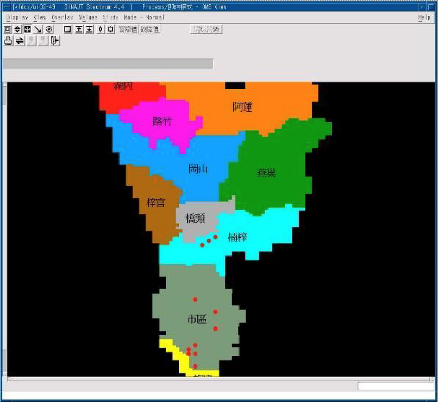
- Map type display for electrical network topology
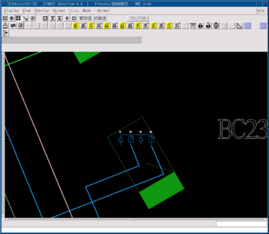
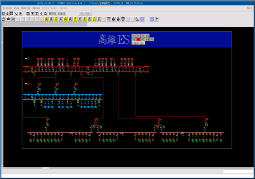
SCADA provides GIS display for operation
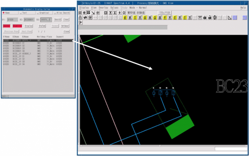
Device Location Function
Easily navigate to required display from alarm event list, equipment tag, road name, landmark, etc.
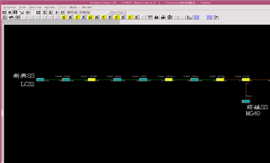
Feeder Schematic Display (SLD)
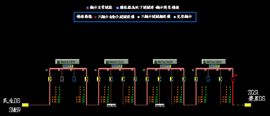
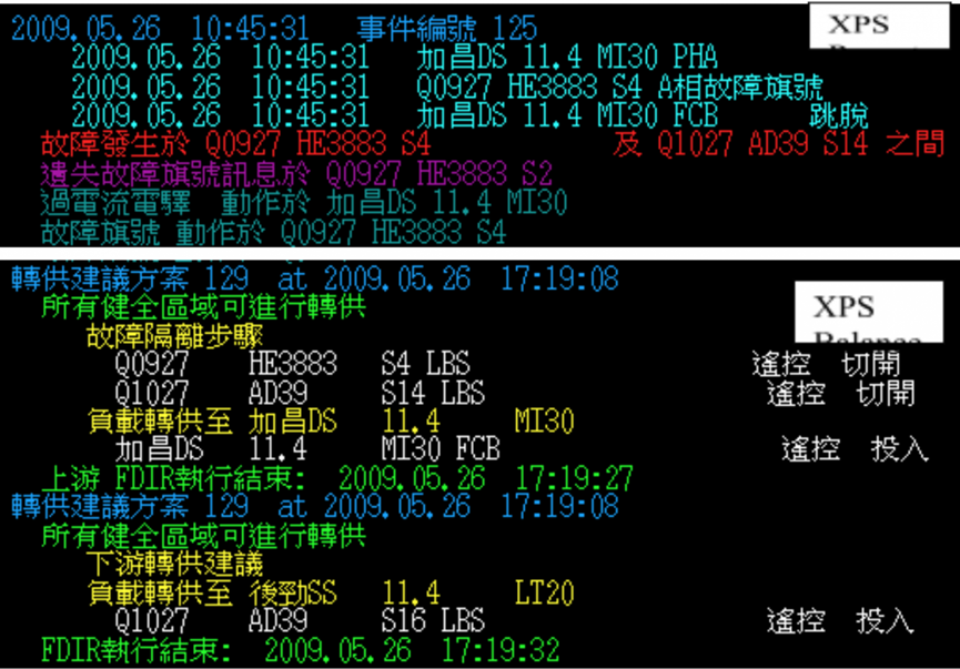
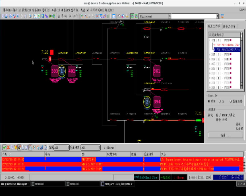
Incident detection, isolation and power recovery (FDIR)
- Automatic/manual detection of accident zones, isolation and upstream power recovery, and provision of re-supply schemes
- Disable all or part of the FDIR function for the entire system/substation/feeder as a unit
- Natural disasters: FDIR prohibition of the whole system
- Substation/main transformer shutdown inspection: disable inspection of feeder FDIR
- Incident handling: FDIR of the accident feeder is disabled or FCB is prohibited from being listed
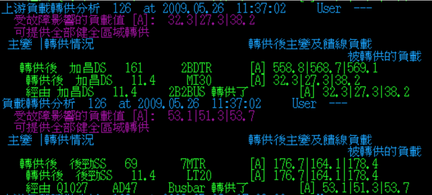
- Simulated accident transfer plan
- Simulation of BUS failure (main transformer failure) calculation and transfer plan
- Designed with Redial network distribution system
- The feeder of the Meshed network system must be set to prohibit the implementation of FDIR function
- The plan will include the judgment of the fault current direction and strengthen the FDIR function
Database incremental update and information exchange
- Software will check the updates in OMS and export into supported format to import into FDCS databse.
- Circuit breaker status in FDCS can feedback to OMS system.
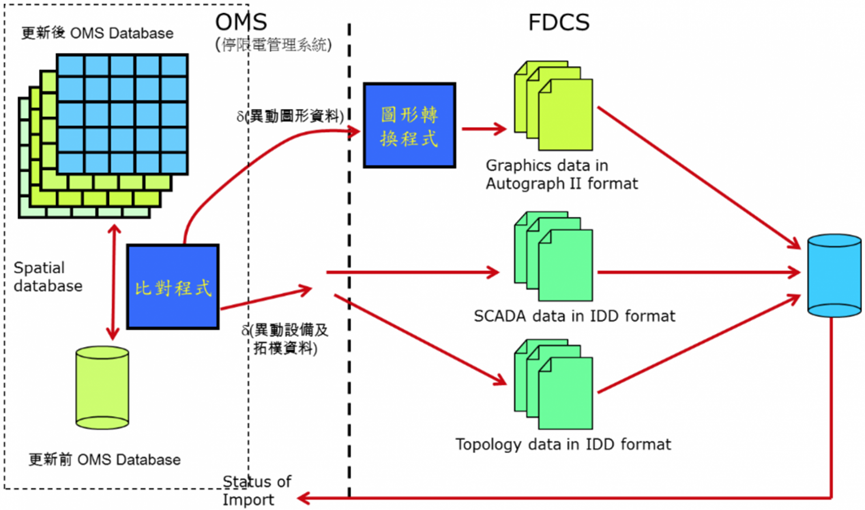
Figure 4.4 Architecture for database incremental update and information exchange
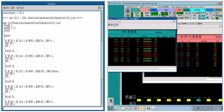
FDCS DTS
Communication Protocols
- ICCP communication (DDCS to FDCS)
- FTP (OMS/DMMS and FDCS conversion files)
- NTP (time synchronization)
- DNP3.0 (downstream communication protocol)
- TCP/IP (10/100/1000Mbps) and UDP (device communication)
Existing system communication architecture
- There is a wide area network (WAN) backbone network between the control centers (distributed as shown in Figure 4.5) planned for all 24 Distribution Branch in Taiwan, and the control centers in all 24 Distribution Branch in Taiwan have local area networks (LAN). The connection is available for data transmission. The backbone network includes optical fiber and optical fiber composite overhead ground wire (OPGW).
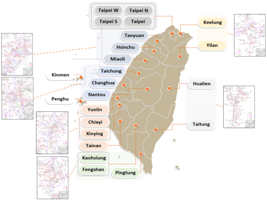
Figure 4.5 Overview of the distribution of control centers in the power distribution area
-
The current communication protocols used for field monitoring equipment are DNP3.0, DNP3.0 Over TCP/IP (Figure 4.6).
-
DNP3.0 is a communication protocol widely used in the industry. The FDCS use DNP3.0 over TCP/IP as the communication between the control center and FRTU and DNP3.0 as the communication between FRTU and PRTU/FTU. When the IEC61850 communication protocol product types and brands increase, the automation equipments and protection equipments in field can adopt this communication protocol to simplify field wiring and data maintenance. As the TCP/IP communication architecture is widely adopted by various wired and wireless communication equipment, the FDCS system of the power distribution feeder uses TCP/IP as the communication architecture.
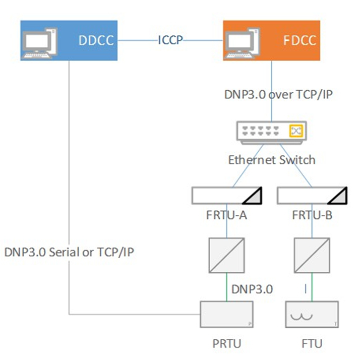
Figure 4.6 Communication between control center and equipment
Promote actual performance
- According to the goal set by the “The Smart Grid Master Plan” of the Bureau of Energy, Ministry of Economic Affairs, 1500 automatic switches monitored must be increased every year from 2022 to 2030. It is expected that the goal of full automation will be achieved by 2030. The total number of automated feeders by the end of 2025 has reached 10,172, and the penetration rate is about 100%. 38,214 feeder automatic switches have been included in the FDCS system monitoring (Figure 4.7).
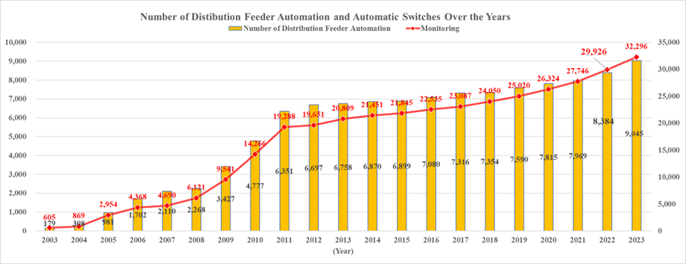
Figure 4.7 The actual performance of the number of automatic feeders and the number of switches
-
The main benefits of Distribution Feeder Automation include reducing manual on-site operations, accelerating power recovery time, reducing operating costs and improving work safety.
Statistics of the number of remote control operations for work and accidental power outages over the years
Application computer, communication, control and other technologies and technologies to build a feeder FDCS system to perform real-time status monitoring, power remote measurement and remote operation of automatic switches of distribution feeders. According to statistics, from 2007 to 2025, the number of operations due to power outages increased from 230 to 6,191, and the number of maintenance operations increased from 6,493 to 134,131, enabling operators to grasp and dispatch power distribution feeders at any time, quickly isolate faults, reduce the scope of power outages, and greatly Reduce the time for dispatching personnel to work on-site in the event of a power outage, and improve the efficiency of the operation of the distribution grid.Smart grid overall planning model scheme “The proportion of the number of units restored within 5 minutes at the downstream end”
According to the content of my country's "Smart Grid Master Plan", the automatic feeder restoration (FDIR) is formulated, and the downstream end of the accident restoration time will account for the number of all automatic feeder restorations from 5 minutes to 17%, and the target will be increased to 2022. 35% within 5 minutes in 2025; 70% within 5 minutes in 2025; 90% within 5 minutes in 2030, and the company has reached 77% in 2025(Figure 4.8).
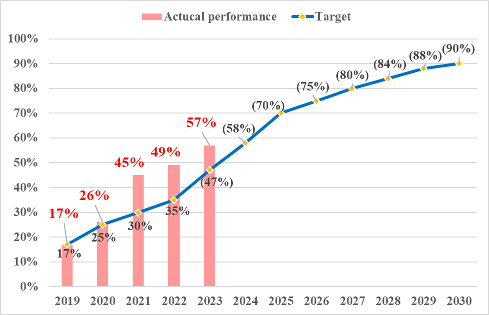
Figure 4.8 The percentage of recharges completed by the automated system within 5 minutes
Improve ADMS system (FDCS system) in response to the future development of smart grid
Promote the inclusion of smart grid functions
- Taiwan is actively promoting the policy of establishing a nuclear-free home by 2025and has set a new goal of increasing the proportion of renewable energy power generation to 20% by 2025. Renewable energy brings the hope of energy transition. TPC has to deal with the grid shock caused by the high penetration rate distributed power supply (DER) in advance.
- In order to create a friendly grid-connected environment, Taiwan Power Company has successively started grid improvement projects to increase the grid-connected capacity of renewable energy, and to avoid the impact of the uncertain characteristics and intermittent characteristics of renewable energy on the grid after the renewable energy is connected to the distribution network. Plan to integrate the power distribution FDCS system and the renewable energy management system and improve the flexibility of dispatching operation through its ability to monitor and integrate various information of the power distribution network.
ADMS continues to improve as a plan
-
Integrate the Data for many distribution systems of TPC
- TPC has commissioned the Taiwan Industrial Technology Research Institute to conduct research on the introduction of Common Information Model (CIM) into smart grid application systems in 2019, and completed the CIM profile (CIM Profile) specification for TPC to build and integrate various The distribution monitoring system information is in the data application analysis platform.
- TPC has also commissioned Taiwan Industrial Technology Research Institute to complete the GIS CIM profile format of the power distribution system. TPC will continue to implement the CIM format data exchange file (CIM Message) of each system of TPC according to this standard.
-
ADMS system continues to promote
- The plan for a new generation of ADMS system has been completed in 2020 to replace the existing FDCS (with ADMS function), and will integrate various power distribution subsystems, GIS map Integration of resources and OMS, FLISR (utilize power flow calculation), Distribution Power Flow calculation, Distribution State Estimation, Feeder Reconfiguration, Active Network Management and other smart grid functions.
- In 2021, the planned ADMS content is entrusted to DNV International Consulting Company to formulate feasible technical specifications, and the public request for comments (RFC) and public request for quotation (RFQ) of technical specifications will be processed. There are international ADMS manufacturers such as Schneider, GE, ABB and MINSAIT ACS. Participate in providing comments on the content of the specifications. In January 2022, the bid is awarded. It contracted by MINSAIT ACS, Taiwan Fixed Network and Hsiang Cheng Electric. It will promote the upgrade of the power distribution system and introduce the MINSAIT ACS PRISM ADMS system. The project is working on solution design in 2022 and it is expected to be launched in 2027.
Implementation of smart grid application functions
Kinmen Distribution Branch pilots FDCS smart grid application platform
- Take the lead in integrating renewable energy across the island
TPC is the first to pilot the introduction of a new generation of ADMS in Kinmen District in 2020 to monitor renewable energy, collect and integrate multiple information on the distribution network. Through the application of the pilot platform, TPC has the ability to manage and control the grid connection of renewable energy. Kinmen ADMS has completed the data capture of the Kinmen renewable energy case (82 PV-GATEWAY installations with a capacity of about 6MW, 2 DG-RTU stations with a capacity of about 3.3MW), accounting for more than 90% of the total installed capacity of Kinmen solar energy, and also captured the Jinmen civil rights feeder 50 Data of distribution line transformers with TTU (the maximum feeder load is about 2.5MVA), in order to completely collect the renewable energy data and user-end power data in Kinmen area, and fully grasp the fluctuation of the system terminal voltage and load. - Import IEC61850
In the Kinmen area, the initial stage will be conducted in the form of a research project. The implementation of the IEC61850 communication standard will collect and monitor the renewable energy information of the photovoltaic (PV) field, and the pilot FTU will use IEC61850 communication. - Verification of FDCS smart grid application functions
Introduce advanced technologies such as power flow analysis and state estimation, and integrate smart monitoring equipment such as smart meter (AMI), transformer information terminal equipment (TTU), fault indicator (FCI), etc., to carry out distribution feeder automation SCADA, FDIR, load forecasting and regeneration The verification of advanced functions of power distribution network management, such as energy management and control, has been completed in 2020.
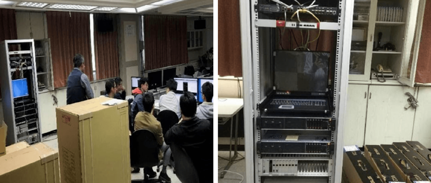
Figure 4.9 Function discussion
System one-line diagram
Accident transfer
Power flow analysis
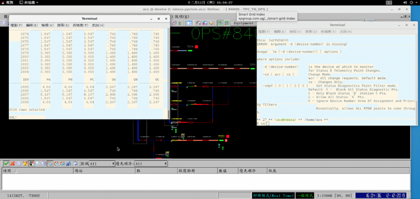
Figure 4.10 System diagram control screen
Taiwan’s industry and TPC cooperate to promote smart grid applications
TPC and the Institute of Nuclear Energy Research, Atomic Energy Council, Executive Yuanjointly develop smart grid application functions, start cross-industry cooperation between domestic power companies and institutes, conduct research on feeder dispatch related technologies for high proportion of renewable energy, and has been developed conduct pilot in Yunlin Distribution Branch.
- Complete the integration of distribution power flow calculation program in FDCS System
In 2020, complete the integration of the distribution power flow calculation program on FDCS System, and propose a feeder transfer proposal, integrate the feeder power flow and line loss programs, and use the feeder test and FDIR in Yunlin area to adjust the feeder margin, Information such as the minimum and maximum voltage mark and location, line loss, etc., will be included in the forwarding plan for operators’ reference.
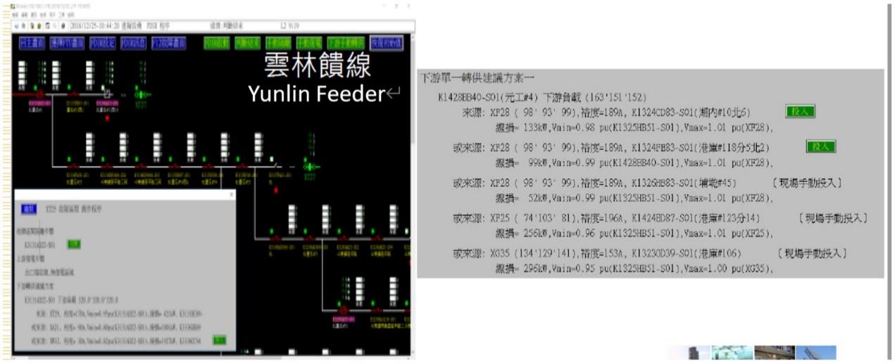
Figure 4.11. Proof of tidal current calculation showing daytime surface
In recent years, as a large number of renewable energy sources are connected to the grid, the intermittent nature of their power generation has led to problems such as voltage fluctuations and three-phase imbalance in the distribution system. When an accident occurs on the feeder, the renewable energy power generation device will suspend power supply, making it difficult to transfer power downstream of the fault point when the load is too large. To this end, an optimal configuration strategy platform for distribution feeder tie switches was developed to equalize the feeder load by adjusting the opening and closing state settings of the tie switches of each feeder in the substation. Taking the substation in Taipower's Yunlin District as an example, the simulation results verified that the regional feeder load rate could be equalized, so as to avoid excessive load in the downstream healthy area of some feeders, thus facilitating the smooth transfer of faults.
- Renewable energy reverse power transmission control function
Summarize the capacity and location of the renewable energy installations and equivalent them to the main line. Use the distribution power flow analysis program to verify the reverse transmission of the renewable energy, showing that the final FTU voltage is higher than the previous one
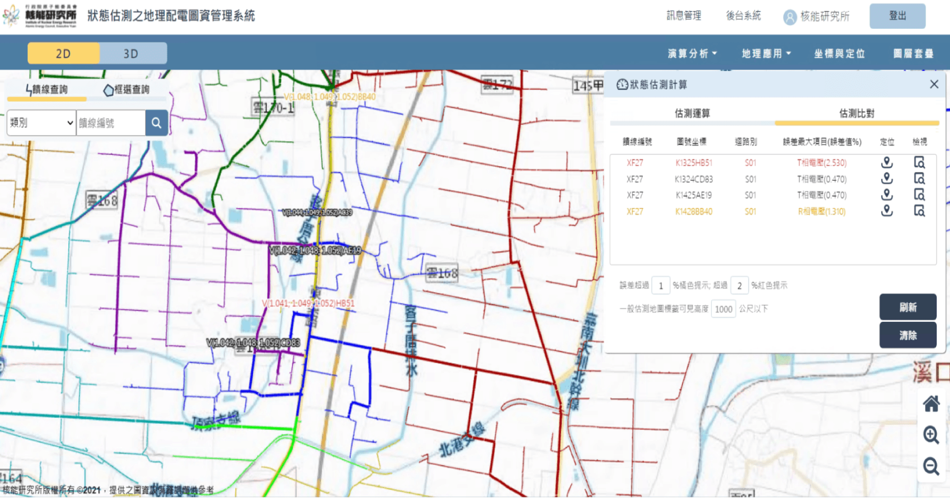
Figure 4.12 Reverse power transmission control of renewable energy
In a complex power distribution system, due to the large number of nodes in the main feeder and branch lines, if you want to master the information of each node, you must install a lot of measuring equipment, which not only increases the cost, but also has a large amount of data in the transmission and collection. certain difficulty. When the proportion of renewable energy is gradually increased, and the node measurement data is limited, it is bound to be difficult to grasp the voltage rise caused by renewable energy power generation, which will affect the quality of power consumption. Therefore, a state estimation technology is developed. This technology can estimate the power generation state of the main and branch lines of the power distribution system, and compare the error value between the estimated result and the on-site measurement value, and at the same time display the estimated result in the geographic map data system ( As shown in Figure 4.12), to help dispatchers grasp the influence of distributed power supply on feeder changes, and check the location of abnormal monitoring equipment.
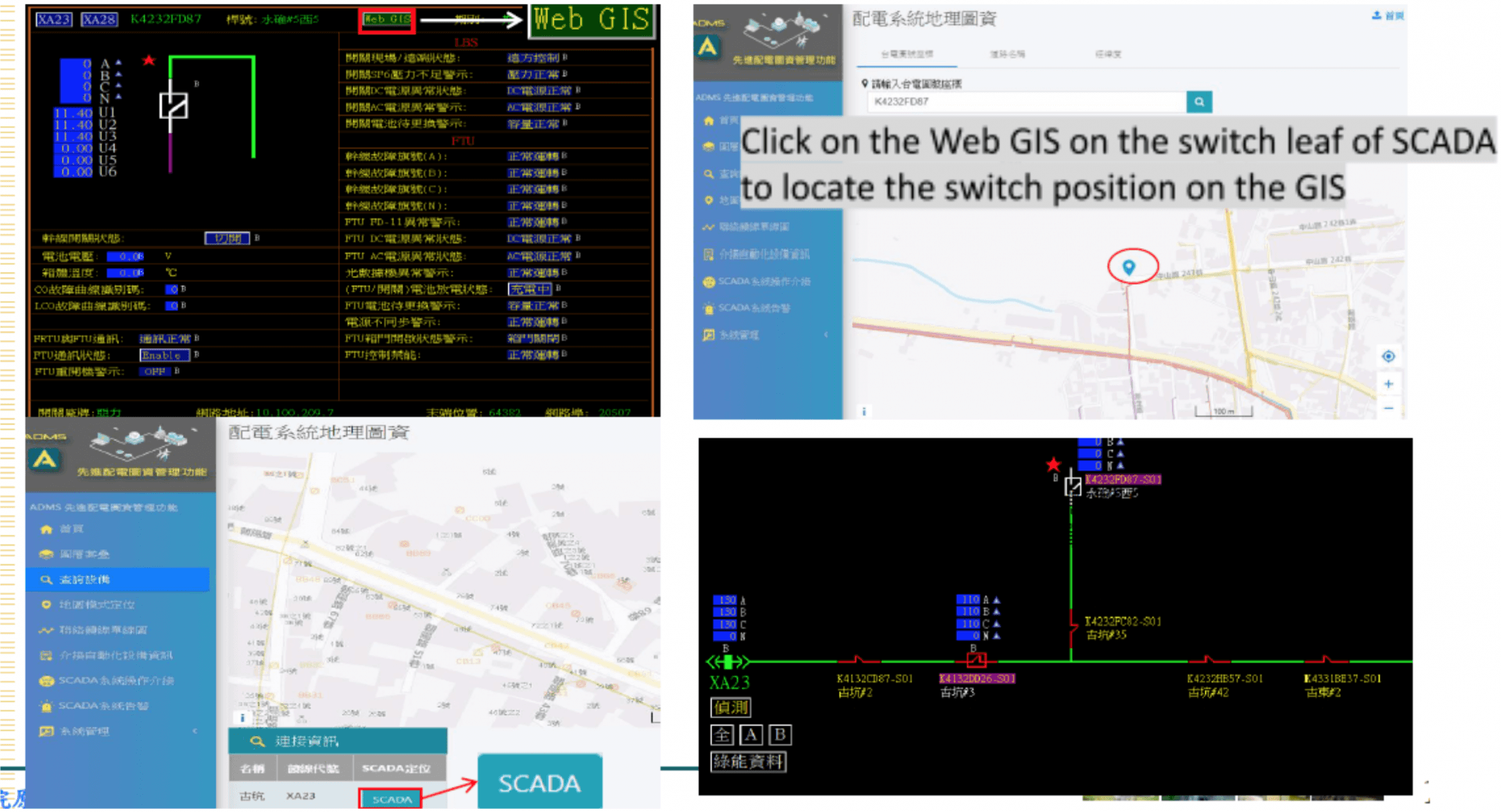
Figure 4.13 Geographic map data system
- Integrate the GIS function integration of the open map platform
The development of the spatial database function of converting data in Oracle into PostgreSQL (open source) has been completed. FDCS feeder data and equipment attributes can be integrated in various open maps (Figure 4.13) to achieve smart grid GIS data application.
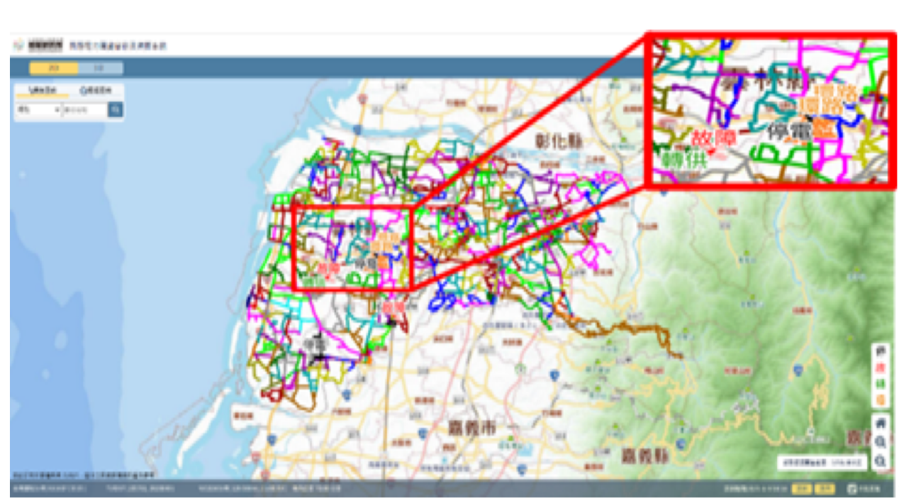
Figure 4.14 Dispatching system geographic map and single-line diagram
Develop a visual feeder dispatching management platform (as shown in Figure 4.14) to provide real-time visual information for dispatchers and emergency repair personnel when faults occur. This technology refers to IEC 61968 and IEC 61970 international standards to formulate a common information model for power distribution equipment. And use the common data format of the common information model to establish the integration of power monitoring and geospatial information, so as to reduce the error between the one-line diagram of the feeder operation on the distribution map and the field equipment, and ensure its correctness and operability.
Green Energy Estimate Monitor System (GEMS)
Taiwan has a maritime island climate, characterized by distinct seasons and frequent afternoon thunderstorms. These weather patterns significantly impact solar photovoltaic (PV) power generation. To quickly detect deviations between actual PV power output and predicted values, visualizations are essential. Additionally, integrating wind and solar power data into a single visualization page provides dispatchers with a comprehensive reference.
Therefore, on the existing Green Energy Estimate Monitor System (GEMS),a solar photovoltaic standard deviation feature has been developed by applying data value-added techniques. It incorporates the concept of standard deviation mathematical models and utilizes historical and current solar photovoltaic generation data. The system calculates the average hourly power generation and the hourly variation in power generation (as indicated by the gray and black dashed lines in the diagram). It then presents the variation by adding or subtracting 1.64 times the standard deviation to create upper and lower trajectories (shown as light green dashed lines). Additionally, the standard deviation of historical hourly power generation variations (represented by the light blue area) is displayed as the range interval. The ramp of power generation every half hour on the monitoring day (that day) is normalized (multiplied by 2) to hourly, and the current situation is displayed quickly through real-time display (green bar).
Analyzing the standard deviation of each period through historical data of different days, the results suggested that 60 days is better. Calculated based on the changes in photovoltaic power generation for each hour in the past 60 days, there is a 90% chance that photovoltaic ramp of power generation for each hour of the day within the upper and lower trajectory of the standard deviation. It can be used as a reference for preparing Fast Responsive Reserve units to prepare Fast Responsive Reserve Units in advance to cope with the impact of photovoltaic power generation by seasonal changes.
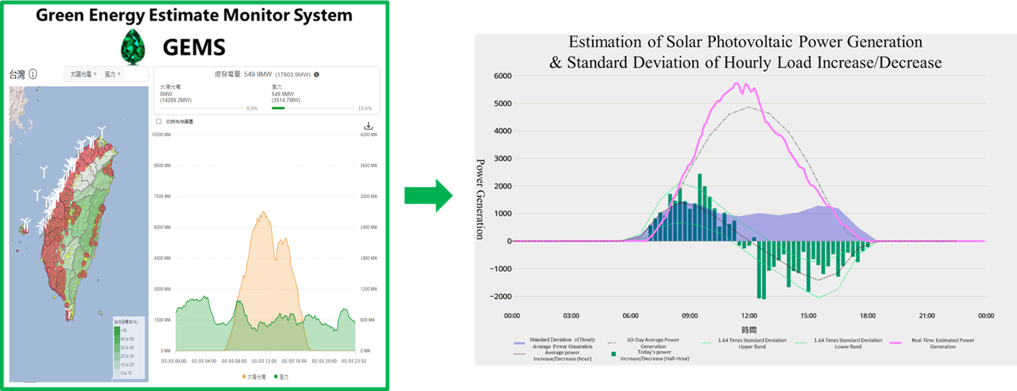
Figure 5.1 Green Energy Estimate Monitor System (GEMS)
Distribution Renewable Energy Advanced Management System (DREAMS)
DREAMS with Smart Inverter
In order to solve the problem of the maximum grid hosting capability of power distribution system limited by strength of power grid and intermittent power generation characteristic of renewable energy system, the “Distribution Renewable Energy Advanced Management System (DREAMS, shown in Figure)” can be used in coordination with smart inverter to adjust the power factor of renewable energy system to absorb the reactive power in order to maintain the voltage quality. In addition to the effective management of the impact of renewable energy on the power distribution system, the simulation analysis of power distribution feeder can verify that, under the same voltage variation constraint, the incorporation of DREAMS in conjunction with the self-adjustment function of smart inverter can enhance the permissible hosting capacity of renewable energy system of the feeder by more than 20%.
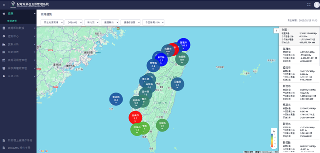
Figure 5.2 Distribution Renewable Energy Advanced Management System (DREAMS)
DREAMS Planning and Construction Schedule
- The power generation information of the sites with renewable energy system installation of more than 500kW will be collected according to TPC DNP3.0 communication protocol. The information shall include power generation volume of active and reactive power, power factor, voltage at Point of Common Coupling (PCC), and relevant setting values. The aforementioned information should be sent back to DREAMS via 4G communication system.
- In the medium-term, in response to the diversification of distributed energy resources, DREAMS management functions will be expanded. In the future, it will collect real-time power information from distribution-level photovoltaic energy storage systems, electric vehicle charging pile management systems, and microgrid systems to provide timely dispatching reference for the dispatch center and also have load Integration and demand control functions.
- In long-term, DREAMS is expected to be interfaced with “Advanced Distribution Management System (ADMS)” to execute remote monitoring of renewable energy site via transmission of control command to the smart inverter of renewable energy in order to enhance the grid resilience and to maintain good power supply quality based on maximization of renewable energy.
DREAMS Planning in Future
The future plan is to adopt DREAMS in coordination with ADMS, so the network topology architecture can be updated in real time according to the switching operation decision of dispatch of power distribution system. And the system impact analysis can be conducted based on the power generation information of renewable energy collected by the renewable energy management system in order to derive the control decision of renewable energy smart inverter. In the end the control station and download the aforementioned control decision to the smart inverter via 4G communication system to achieve the modulation of renewable energy system power output in order to provide the auxiliary service function required by maintaining the safe operation of power grid.
Introduction to Taiwan's real-time inertia measurement and monitoring system
In response to the trend of energy transition, the proportion of renewable energy generation has been continuously increasing in recent years. The inherent instability of renewable energy generation makes the power system more susceptible to frequency fluctuations. In this context, the power system's "inertia" acts like an invisible stabilizer, primarily originating from the rotational inertia of traditional generator sets. It can temporarily maintain grid frequency stability during sudden changes in power supply and demand, which is crucial for the stable operation of electrical equipment, especially for the semiconductor industry. However, the rapid development of low-inertia renewable energy sources like solar and wind power is reducing the overall grid inertia, affecting stability.
To address this challenge, in addition to regulating grid frequency through energy storage systems, Taipower Company is actively monitoring the grid's "inertia." Since December 2022, Taipower has collaborated with a British manufacturer to deploy 10 high-precision frequency measurement units (XMUs, eXtensible Measurement Units) across Taiwan and one energy storage power modulator. This collaboration assists in measuring system inertia data. The principle of this inertia measurement involves the power modulation device installed at Taipower's Dongshan Energy Storage Project continuously injecting disturbance into the power system. The XMU devices deployed across Taiwan then instantaneously collect frequency data during the disturbance. This data is then analyzed in real-time by computers to determine the current system inertia, helping power dispatchers understand the real-time status of Taiwan's power system. According to the latest power system monitoring data, during the Chinese New Year holiday from New Year's Eve to the second day of the new year in 2025, inertia significantly decreased due to reduced industrial power consumption and increased renewable energy penetration. The data (detailed in Figure 6.2) shows that the system inertia reached its lowest point at noon on the first day of the new year, dropping to 137 GWs. This value represents a significant discrepancy compared to the normal system inertia range of approximately 180 to 220 GWs. These data clearly indicate that during the Chinese New Year period, if the proportion of renewable energy generation significantly exceeds that of traditional generator sets, grid inertia may substantially decrease, posing a significant challenge to grid stability.
In summary, inertia is a crucial factor in maintaining the stable operation of the power system. With the development of renewable energy, we need continuous innovation and new methods to maintain grid stability. Taipower Company is actively responding to these challenges by measuring and analyzing inertia, ensuring Taiwan's power supply remains stable and reliable.
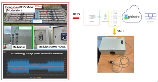
Figure 6.1 Real-time inertia measurement project architecture diagram
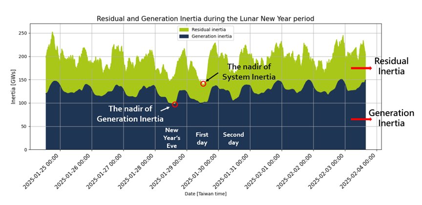
Figure 6.2 2025 Lunar New Year Inertia Measurement Results